New_category: News

News

  • How to Wire A Circuit Using A Piezo Switch: Robust Industrial Connections

    How to Wire A Circuit Using A Piezo Switch: Robust Industrial Connections

    [vc_row][vc_column][vc_column_text css=””]


    Crafting a circuit with a piezo switch demands meticulous precision in component selection and connection integrity, particularly within industrial settings where unwavering reliability is paramount. Industrial piezo switches leverage the piezoelectric effect—transforming mechanical pressure into an instantaneous electrical signal—to deliver unparalleled operational longevity. Yet, without proper wiring, even the most robust IP68/IP69K-rated units can fall short. This comprehensive guide unpacks every critical stage: from grasping piezo switch fundamentals and preparing components, through step-by-step 2-wire and 3-wire connections, microcontroller integration, and troubleshooting. You’ll gain insights into the distinctions between momentary and latching functions, uncover best practices for signal conditioning and grounding, and delve into advanced industrial considerations. Throughout, we highlight Langir’s advanced, customizable bulk piezo switch solutions for large-scale projects, ensuring you’re equipped to wire circuits that meet the most stringent performance and durability benchmarks.


    Understanding the Piezo Switch: Its Core Functionality in Industrial Circuitry

    A piezo switch is a solid-state electronic component that converts mechanical force via a piezoelectric element into an electrical signal, delivering contactless operation and unparalleled durability. When mechanical pressure compresses the piezoelectric crystal, it produces a precise voltage pulse that activates a Field-Effect Transistor (FET), seamlessly closing or opening the circuit for over 50 million cycles, entirely without moving parts. This robust mechanism guarantees rapid response and unwavering resilience in the most demanding environments, making piezo switches the optimal choice for critical industrial control panels and advanced automated machinery.

    Understanding the Piezo Switch Its Core Functionality in Industrial Circuitry

    Get a quote for custom Piezo switches from Langir


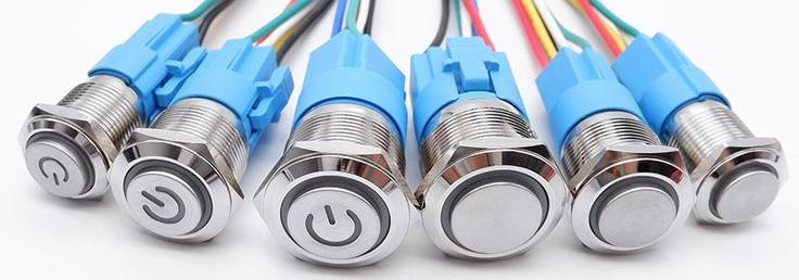
    Piezo Switch Anatomy: Dissecting Its Key Components

    A piezo switch integrates a piezoelectric element, a FET, a resistor, and a capacitor within a robust, sealed package to ensure flawless switching performance. The piezoelectric element (ceramic or crystal) generates an electrical charge under mechanical stress, the FET converts that charge into a precise circuit-controlling action, the resistor mitigates surge current, and the capacitor refines the pulse duration. The meticulous specification of each component guarantees consistent actuation force and precise pulse width, ensuring dependable signal output even under the most extreme conditions.


    The Piezoelectric Effect: Unveiling the Signal Generation Mechanism

    The piezoelectric effect occurs when mechanical pressure applied to certain crystalline materials induces an electrical charge on their surfaces. In a piezo switch, a precise force of 3–5 N compresses the piezo element, generating a transient voltage spike, meticulously filtered and amplified by the integrated resistor-capacitor network before precisely driving the FET gate. This instantaneous conversion from mechanical stress to electrical pulse eliminates mechanical bounce and wear, delivering unparalleled solid-state reliability, rated up to IP69K, across wet, dusty, or high-temperature industrial environments.


    Foundations: Piezoelectric Effect and Sensor Technology

    Piezoelectric materials produce an electrical charge under mechanical stress, a fundamental principle in advanced sensor technology. This effect is precisely engineered into piezo switches, which transform pressure into a reliable electrical signal, ensuring robust contactless operation and exceptional durability across diverse industrial applications.


    IEEE Xplore, “Piezoelectric Sensors: Principles and Applications” (2022)

    This research offers critical foundational knowledge on the piezoelectric effect, which is integral to the robust functionality of piezo switches discussed in this guide.


    Optimizing Performance: Why Proper Wiring is Critical for Piezo Switches

    Proper wiring is paramount for preserving signal integrity, mitigating noise interference, and guaranteeing the switch’s long-term reliability. Incorrect polarity, loose connections, or improper grounding can result in compromised pulses, erratic switching behavior, or even premature component failure. By meticulously adhering to specified voltage and current ratings, deploying shielded wiring, and rigorously following grounding best practices, you safeguard the switch’s rapid response and extended service life, which are absolutely critical for minimizing downtime in demanding industrial operations.


    Foundational Principles: Industrial Wiring and Circuit Design

    Proper wiring is indispensable for optimizing the performance and reliability of piezo switch circuits, particularly within demanding industrial environments. Correct polarity, secure connections, and appropriate grounding are fundamental to preventing signal interference and ensuring the extended longevity of the switch, thereby significantly reducing costly downtime in industrial operations.


    National Electrical Code, “Wiring Methods for Industrial Installations” (2023)

    This code offers authoritative guidelines for industrial wiring, which are critical for the precise and compliant implementation of piezo switch circuits.


    Assembling Your Circuit: Essential Components for Piezo Switch Wiring

    Grasping the precise components required and how their specifications impact overall performance is the foundational step toward achieving a flawless, high-performance piezo switch circuit.

    Assembling Your Circuit Essential Components for Piezo Switch Wiring

    Get a quote for custom Piezo switches from Langir


    Core Electrical Components for a Basic Piezo Switch Circuit

    A functional piezo switch circuit requires these core components:


    1. Robust Piezo Switch (IP68/IP69K-rated solid-state push button)
    2. Stable DC Power Supply (5–60 V, precisely matching the switch’s voltage rating)
    3. Appropriate Load (e.g., LED, relay coil, PLC input module)
    4. Series Resistor (100 Ω–1 kΩ, crucial for limiting inrush current)
    5. Shunt Capacitor (0.01 µF–0.1 µF, essential for precise pulse shaping)

    By selecting components with precisely matched voltage and current ratings, you ensure that the piezo switch pulses are reliably delivered to the load without any risk of overstress or degradation.


    Essential Tools and Materials for Seamless Wiring

    Before starting assembly, gather these tools and supplies:


    • Precision wire strippers for accurate insulation removal
    • High-quality soldering iron and rosin-core solder for robust, lasting joints
    • Digital multimeter to meticulously verify continuity and voltage levels
    • Durable heat-shrink tubing for superior insulation and strain relief
    • EMI-shielded two- or three-core cable to effectively minimize electromagnetic interference
    • Reliable crimp connectors or industrial-grade terminal blocks for secure, service-friendly connections

    Proper tooling and materials are indispensable for streamlining installation and ensuring unwavering long-term circuit integrity.


    How Component Specifications Impact Your Wiring Choices

    Voltage rating governs insulation thickness and optimal cable selection, while current rating determines conductor gauge and appropriate resistor sizing. Resistance and capacitance values precisely control pulse amplitude and duration, directly influencing signal clarity and reliability. Higher capacitance results in longer pulse widths, though potentially at the expense of faster reset times, whereas lower resistance minimizes voltage drop but can increase surge current. Meticulously aligning each attribute with the switch’s official datasheet is crucial to prevent underperformance or the risk of component damage in the most demanding industrial environments.


    Implementing a Basic 2-Wire Piezo Switch Circuit

    Connecting a piezo switch in a straightforward two-wire configuration provides a direct, efficient on/off signal to a load with minimal wiring complexity, ideal for straightforward applications.


    Step-by-Step Guide: Connecting a 2-Wire Piezo Switch


    1. Precisely strip 6 mm of insulation from each wire end.
    2. Securely solder a series resistor between the switch’s positive terminal and the power supply’s positive lead.
    3. Connect the switch’s negative terminal directly to the power supply’s negative (ground).
    4. Connect the load’s positive input to the switch’s output junction.
    5. Link the load’s negative side to the power supply’s negative rail.
    6. Thoroughly insulate all solder joints with high-quality heat-shrink tubing for protection.

    This straightforward layout leverages the switch to precisely break or make the supply path, ensuring reliable and instantaneous on/off switching.


    Interfacing the Piezo Switch with the Load in a 2-Wire Setup

    In a 2-wire design, the piezo switch is positioned directly inline with the power supply and the load: the series resistor on the positive line safeguards the piezo element, while the switch itself completes the circuit upon actuation. This direct connection significantly simplifies both installation and subsequent troubleshooting.


    Critical Polarity and Grounding Considerations

    Piezo switches are inherently non-polarized at their core sensor element, but the integrated FET circuitry demands precise polarity. Always meticulously adhere to the datasheet’s positive/negative markings to prevent irreversible FET gate damage. Ground loops can introduce detrimental noise, so ensure grounds are tied at a single star point and utilize shielded cable to effectively minimize EMI. Proper grounding ensures the switch’s robust immunity to electrical interference, crucial for reliable operation in industrial environments.


    Achieving Enhanced Control: Wiring a 3-Wire Piezo Switch Circuit

    A three-wire setup introduces a dedicated signal output line, empowering buffer stages or advanced control systems to distinguish actuation events with superior precision.


    Integrating a 3-Wire Piezo Switch with Power and Control Systems: Step-by-Step


    1. Securely attach the red wire to the DC power supply’s positive terminal.
    2. Connect the black wire to the supply’s negative (ground) reference point.
    3. Connect the yellow signal wire to a pull-up resistor, then route it to the control system input.
    4. Verify that the series resistor is correctly positioned between the red wire and the switch’s internal circuitry.
    5. Route all wiring through an EMI-shielded conduit and secure connections with robust cable glands to ensure IP68 sealing.


    Transmitting Signals: How the Piezo Switch Communicates with a Control System

    In a 3-wire configuration, the piezo switch generates a precise voltage pulse on the dedicated signal output line upon actuation. The control module’s input interprets this transient pulse, initiating critical actions such as machine start, safety interlock release, or precise data logging.


    Defining the Roles: Each Wire in a 3-Wire Configuration


    Wire Color Role Specification
    Red Power Supply Input Provides 5–60 V DC input to the switch’s internal circuitry
    Black System Ground Reference Establishes the 0 V reference, ideally with a single-point ground connection
    Yellow Signal Output Line Delivers a voltage pulse (up to supply voltage) via an external pull-up resistor


    Seamless Integration: Connecting a Piezo Switch with a Microcontroller (e.g., Arduino)

    Connecting a piezo switch to an Arduino enables sophisticated programmable logic for advanced control, precise diagnostics, or critical data acquisition tasks.

    Seamless Integration Connecting a Piezo Switch with a Microcontroller (e.g., Arduino)

    Get a quote for custom Piezo switches from Langir


    Wiring Procedure: Connecting a Piezo Switch to an Arduino


    1. Connect the piezo switch’s positive lead to the Arduino’s 5V pin via a 220 Ω current-limiting resistor.
    2. Securely tie the switch’s negative terminal to one of the Arduino’s GND pins.
    3. Route the switch’s signal output to an available analog input pin (e.g., A0).
    4. Within the Arduino IDE, configure the selected pin as INPUT_PULLDOWN, or alternatively, employ an external pull-down resistor.
    5. Upload robust code designed to read analog values exceeding a predefined threshold, thereby accurately detecting actuation events.

    This straightforward wiring enables the microcontroller to precisely sample voltage pulses and execute custom, programmed routines with each actuation.


    Processing the Signal: Microcontroller Interaction with the Piezo Switch

    When force is applied, the piezo element produces a distinct voltage spike, which is then interpreted by the analog input pin. The microcontroller’s ADC converts this analog level into a precise digital value, which firmware compares against a meticulously predefined threshold. Upon exceeding the threshold, the code debounces the input, confirms a valid actuation, and triggers the desired programmed action—such as illuminating an LED, transmitting a serial message, or toggling a relay output.


    Optimizing Signal Conditioning and Noise Reduction: Best Practices


    • Integrate a 0.01 µF to 0.1 µF capacitor in close proximity to the analog input to effectively filter high-frequency noise.
    • Employ twisted-pair or robust shielded cable for the signal line to significantly minimize electromagnetic interference (EMI).
    • Implement a software debounce routine of 10–50 ms to reliably reject spurious pulses and ensure stable readings.
    • Isolate analog and digital grounds, connecting them at a single star point to meticulously avoid detrimental ground loops.
    • Routinely calibrate the threshold within your code to precisely account for potential environmental vibration or temperature shifts.


    Distinguishing Wiring: Momentary vs. Latching Piezo Switch Functions

    Momentary and latching piezo switches exhibit fundamentally distinct operational behaviors: one instantly reverts to its open state upon release, while the other toggles its state with each subsequent actuation.


    Wiring a Momentary Piezo Switch Circuit

    A momentary switch completes the circuit solely for the duration of applied force. Wire it precisely as outlined for the basic 2-wire setup, ensuring the correct series resistor and meticulous grounding. Upon actuation, the FET remains active only while pressure is sustained. Release of pressure instantly resets the circuit. This configuration is ideally suited for pulse-triggered machine controls and critical safety interlocks.


    Wiring for Sustained State: The Latching Piezo Switch

    Latching piezo switches incorporate sophisticated internal flip-flop circuits: a single actuation toggles the FET’s state (on or off). Connect power and ground precisely as in the 2-wire design, but ensure the switch’s dedicated control line is securely tied to the latch logic input. The switch’s internal capacitor retains charge to maintain its state until the subsequent actuation. Latching behavior is perfectly suited for robust on/off toggles in harsh industrial environments where mechanical bounces must be absolutely eliminated.


    Real-World Applications: Practical Uses for Each Wiring Type


    • Momentary: Critical emergency stop buttons, operator prompts, and precise moment-driven inputs.
    • Latching: Reliable power on/off controls, intuitive mode selection toggles, and robust indicator light circuits.

    Selecting the correct wiring for its intended function is paramount for ensuring optimal operational clarity and stringent safety compliance in industrial automation.


    Resolving Common Wiring Issues in Piezo Switch Circuits

    Even meticulously designed circuits can encounter operational faults over time; however, systematic troubleshooting can swiftly restore peak performance.


    Diagnosing and Resolving: No Output Signal

    A missing pulse frequently indicates open connections, incorrect polarity, or compromised components. Meticulously verify continuity with a digital multimeter, inspect for reversed power leads on the FET, and confirm that all resistor and capacitor values precisely match the switch’s datasheet specifications. Carefully reflow any suspect solder joints and retest the circuit. Should the piezo element itself be damaged, immediate replacement with a new, robust IP68-rated unit is essential.


    Addressing Erratic Behavior in Piezo Switch Wiring

    Intermittent pulses typically originate from electromagnetic interference (EMI), detrimental ground loops, or inadequate signal conditioning. Deploy robust shielded cable, strategically relocate wiring away from high-voltage lines, integrate a snubber capacitor across the analog input, and implement sophisticated software debouncing routines. Ensuring a pristine ground reference and meticulous cable routing will effectively eliminate the majority of signal instability issues.


    Detecting and Rectifying Short Circuits: A Step-by-Step Approach

    Shorts typically manifest as fused resistors or blown fuses on the supply line. Immediately shut down all power, meticulously inspect wiring for any exposed conductors or damaged insulation, and systematically isolate sections of the circuit using a multimeter’s continuity mode. Replace all damaged wiring and protective components, then carefully reenergize the circuit at a low voltage to confirm the repair before resuming full operational capacity.


    Langir’s Expertise: Custom Piezo Switch Solutions for Industrial Wiring Demands

    Langir specializes in tailored piezo switch manufacturing and efficient bulk ordering to precisely meet unique industrial requirements, seamlessly combining unparalleled endurance with highly flexible design options.


    Tailored Solutions: Customization Options for Piezo Switch Wiring

    Choose from a comprehensive range of housing sizes, bezel styles, actuation forces, and color options to perfectly align with your specific panel dimensions and operator preferences. Langir can expertly integrate specialized resistor-capacitor networks for precise custom pulse widths or embed robust connectors for seamless plug-and-play installations. Each design is meticulously sealed to IP69K, guaranteeing unwavering performance in the most demanding food-grade, marine, or heavy-duty automation environments.


    Optimizing Large-Scale Projects: The Benefits of Bulk Ordering

    Gain access to highly competitive volume pricing for projects involving thousands of switch points, streamline procurement with consolidated, efficient shipments, and significantly reduce lead times through optimized, repeatable production runs. Langir’s robust manufacturing capacity supports orders from 100 to 100,000 units, ensuring consistent, superior quality across every batch for critical large assembly lines or extensive distributed control installations.


    Connecting with Langir: Custom Quotes and Expert Support

    For expert personalized guidance and competitive volume pricing, visit our dedicated Request a Custom Piezo Switch Quote page to connect directly with our specialized engineering team. Whether you require detailed technical specifications, precise 3D CAD files, or custom-tailored actuation profiles, Langir provides responsive, expert support to ensure your project remains precisely on schedule.

    Effective piezo switch wiring demands precise component selection, meticulously clear signal paths, and robust mechanical integration to achieve long-lasting, virtually maintenance-free operation in the most demanding industrial settings. By mastering 2-wire and 3-wire configurations, optimizing microcontroller interfaces, and implementing function-specific layouts, you ensure every actuation remains impeccably clean, consistently reliable, and inherently immune to harsh environmental stresses. With Langir’s comprehensive bulk and customization services, your industrial wiring projects gain unparalleled technical excellence and unwavering supply chain reliability—these are the critical elements for achieving sustained production uptime and enhanced operational safety.


    [/vc_column_text][/vc_column][/vc_row][vc_row][vc_column][vc_zigzag][/vc_column][/vc_row][vc_row][vc_column]

    Get Custom Quote
    We’ll get back to you within 12 hours.
    Drag & Drop Files, Choose Files to Upload You can upload up to 3 files.
    [/vc_column][/vc_row][vc_row][vc_column][vc_zigzag][/vc_column][/vc_row]

  • How to Wire A 16mm LED Push Button Switch: Industrial & Custom Control Panels

    How to Wire A 16mm LED Push Button Switch: Industrial & Custom Control Panels

    [vc_row][vc_column][vc_column_text css=””]


    Struggling with inconsistent LED illumination or unreliable switch activation in your industrial systems? Precision wiring of a 16mm LED push button switch is paramount for seamless control and clear status feedback in demanding environments. This comprehensive guide will equip you with a deep understanding of 16mm LED push button switch functionality, essential tools, critical safety protocols, and detailed step-by-step wiring instructions for 2-, 4-, and 5-pin configurations. We’ll also cover advanced voltage considerations, precise resistor calculations, effective troubleshooting techniques for common issues, and highlight why Langir’s robust L16 series switches are the preferred bulk solution for leading manufacturers. Let’s delve into switch architecture, illumination variations, optimal wiring practices, fault diagnosis, and how to secure a custom quote from Langir.


    Understanding the 16mm LED Push Button Switch: Functionality and Core Principles

    A 16mm LED push button switch integrates a durable mechanical actuator with integrated illumination, providing both tactile control and visual feedback for critical circuits, particularly in challenging industrial settings. These switches typically feature an LED (available in dot, ring, or bi-color options) and dedicated terminals for common (C), normally open (NO), and normally closed (NC) contacts, alongside specific LED leads. Actuating the button precisely completes or interrupts the NO/NC circuit, while the LED illuminates consistently when correct power and polarity are applied. A thorough understanding of each component is fundamental for achieving reliable operation and unambiguous status indication.

    Understanding the 16mm LED Push Button Switch Functionality and Core Principles

    Get a quote for custom LED push button switches from Langir


    Key Components and Terminal Identification for 16mm LED Push Button Switches

    Before commencing any wiring, a clear understanding of the primary components and their respective functions is essential.

    Component Overview:


    • Actuator: The robust 16mm metal or plastic button, engineered for precise tactile engagement and switch toggling.
    • Housing: A rugged, often waterproof metal body, typically rated IP65–IP68, designed for anti-vandal applications and demanding industrial environments.
    • Common Terminal (C): The primary input terminal for the switch contacts, serving as the connection point for the power or signal source.
    • Normally Open (NO): The contact that closes upon actuation, establishing a connection to deliver power or a signal to the connected load.
    • Normally Closed (NC): The contact that opens upon actuation, interrupting the circuit when the switch is activated.
    • LED Anode (+): The positive input terminal specifically for the LED illumination circuit.
    • LED Cathode (–): The negative return terminal for the LED, typically connected to ground or the negative power rail.


    LED Component Integration and Functionality

    LED push button switches seamlessly integrate various LED types—dot, ring, or bi-color—alongside dedicated terminals for common (C), normally open (NO), normally closed (NC) contacts, and specific LED leads. Actuating the switch precisely completes or interrupts the NO/NC circuit, while the LED illuminates reliably when supplied with correct power and polarity, delivering essential visual feedback and enhanced control across diverse industrial applications.


    Langir Electric, L16 Series Product Information

    This foundational information underpins a comprehensive understanding of the 16mm LED push button switch’s critical components and operational principles.

    Collectively, these components constitute a fundamental control element, providing clear status indication through integrated illumination and precise switching. Our next section will delineate the critical differences between momentary and latching actions and their implications for wiring configurations.


    Momentary vs. Latching 16mm LED Push Button Switches: Functional Distinctions

    The distinction between momentary and latching functions dictates the precise behavior of the switch contacts following actuation.


    Switch Type Action Upon Actuation Action Upon Release Wiring Implications
    Momentary Contacts engage only while depressed Returns to default state upon release Connect NO to load; power flow through C is established only during depression.
    Latching Contacts toggle state with each actuation Maintains new state until re-actuated Utilize NO or NC for persistent toggle control; requires continuous power supply.

    Momentary switches revert to their default state upon release, making them optimal for transient controls such as start/stop functions. Conversely, latching switches alternate their state with each actuation, proving ideal for persistent on/off toggles. A clear understanding of these operational modes is crucial for correctly integrating the appropriate terminals into your machine’s control circuitry.


    Impact of LED Illumination Types on Wiring Configurations

    The chosen LED illumination style directly influences both wiring complexity and the nature of visual feedback provided:


    • Dot LED: Features a single, centralized light source, requiring only two wires (anode/cathode) for operation.
    • Ring LED: Encircles the actuator, utilizing two wires to provide a more diffused and uniform illumination.
    • Bi-color LED: Incorporates two anodes sharing a common cathode, or vice versa, necessitating three wires for dual-color status indication.

    Wiring for bi-color LEDs typically involves mapping each anode to distinct power sources, such as those for red and green indications. The selection of the appropriate illumination type is critical, as it directly dictates the configuration of your LED supply wiring and the necessary resistor calculations.

    This foundational overview of switch anatomy seamlessly transitions into the critical preparation phase, encompassing essential tools, rigorous safety measures, and optimal workspace setup.


    Essential Tools and Critical Safety Protocols for 16mm LED Push Button Switch Wiring

    Prior to engaging with any electrical circuits, it is imperative to assemble the correct tools and rigorously adhere to fundamental electrical safety protocols to safeguard both personnel and equipment.

    Essential Tools and Critical Safety Protocols for 16mm LED Push Button Switch Wiring

    Get a quote for custom LED push button switches from Langir


    Required Tooling for Optimal Wiring Execution

    The following essential tools are required to precisely strip, solder, test, and insulate electrical connections:


    1. Precision wire strippers for accurate insulation removal.
    2. A soldering iron (25–40 W) equipped with a fine tip, ensuring robust and secure solder joints.
    3. A comprehensive heat shrink tubing set, offering assorted diameters for superior insulation and strain relief.
    4. A high-quality multimeter, indispensable for continuity checks and precise voltage verification.
    5. Certified safety glasses, providing essential protection against solder splatter and other potential hazards.

    Equipping yourself with the appropriate tools is fundamental to achieving clean, reliable wiring that maintains integrity even under conditions of vibration, moisture, or other environmental stressors.


    Critical Electrical Safety Measures During Wiring Procedures

    Adhere to fundamental precautions when working on control panels:


    • Always ensure the main power supply is completely disconnected before initiating any wiring or testing procedures.
    • Employ wire gauges that are correctly rated for the intended current (e.g., 22–18 AWG for LED circuits, 16–14 AWG for load circuits).
    • Rigorously insulate all exposed conductors using heat shrink tubing or appropriate terminal boots to prevent shorts.
    • Confirm correct polarity and verify the complete absence of voltage with a multimeter prior to any soldering operations.

    Adhering to these critical safety steps is paramount for preventing short circuits, electrical shocks, and component damage, thereby ensuring a secure and efficient wiring process.

    With the necessary tools prepared and stringent safety protocols established, the subsequent section will guide you through precise wiring methodologies for 2-, 4-, and 5-pin switch configurations.


    Wiring Methodologies for Diverse 16mm LED Push Button Switch Configurations

    Regardless of whether you are working with a straightforward 2-pin indicator or a complex 5-pin control switch, these detailed, step-by-step instructions will ensure the accurate setup of power, load, and LED connections.


    Wiring a Basic 2-Pin 16mm LED Push Button Switch

    A 2-pin switch is exclusively equipped with LED leads, typically for an “always-on” indicator function. Proceed with the following steps:


    1. Precisely strip 5mm of insulation from each lead.
    2. Solder the anode lead to the positive voltage supply (+V, e.g., 24 VDC) via an appropriately calculated resistor.
    3. Solder the cathode lead securely to ground (0 V).

    This configuration results in a continuously illuminated LED, serving as an effective power-on indicator within your control panel.


    Wiring a 4-Pin 16mm LED Push Button Switch with Independent LED Control

    This configuration utilizes four terminals: two dedicated to the switch contacts (Common/Normally Open) and two for the LED illumination circuit:


    1. Connect the positive terminal of your power source to the Common (C) terminal.
    2. Route the Normally Open (NO) terminal to the positive input of your intended load.
    3. Solder the LED anode to the positive voltage supply (+V) through a correctly sized resistor.
    4. Connect the LED cathode securely to ground.

    This setup ensures that actuating the button activates your load, while the LED illumination remains independently controllable, allowing the indicator to be continuously on or off as required.


    Wiring a 5-Pin 16mm LED Push Button Switch with NO/NC Terminals

    A 5-pin switch incorporates an additional Normally Closed (NC) terminal, enabling alternate control functionalities:


    1. Connect the Common (C) terminal to the positive rail of your control power supply.
    2. Route the Normally Open (NO) terminal to the device’s positive input for activation upon switch depression.
    3. Route the Normally Closed (NC) terminal to an alternate circuit as required (e.g., an alarm system that deactivates upon switch actuation).
    4. Solder the LED anode to the positive voltage supply (+V) via a resistor, and connect the cathode to ground.

    This comprehensive wiring scheme facilitates dual-circuit control alongside integrated LED feedback, making it ideal for sophisticated panel functions and complex control systems.


    Integrating LED Illumination: Constant On vs. Load-Dependent Activation

    An “always-on” LED remains continuously illuminated irrespective of the switch’s contact state, whereas an “on-with-load” LED activates only when the switch engages the primary circuit. Select your wiring configuration based on the desired feedback mechanism:


    • Constant Illumination: The LED circuit is connected directly to the power supply rails, independent of the Common (C) and Normally Open (NO) contacts.
    • Load-Dependent Illumination: The LED anode is connected to the Normally Open (NO) terminal, with the cathode tied to ground, ensuring illumination synchronizes with switch activation.

    The choice between these methods should be predicated on whether continuous status indication or activity-based feedback is required for your application.


    Calculating the Optimal Resistor Value for LED Illumination

    To ensure the longevity and optimal performance of the LED, the correct resistor value must be precisely calculated using Ohm’s Law: .


    Supply Voltage (Vs) LED Forward Voltage (Vf) Desired Forward Current (If) Calculated Resistor Value R = (Vs–Vf)/If
    12 V 2 V 10 mA (12 – 2) / 0.01 = 1,000 Ω
    24 V 2 V 10 mA (24 – 2) / 0.01 = 2,200 Ω
    220 V 3.2 V 5 mA (220 – 3.2) / 0.005 = 43,360 Ω


    Precision Resistor Calculation for LED Illumination

    For optimal LED protection and performance, calculating the precise resistor value using Ohm’s Law (R = (Vs – Vf) / I) is paramount. This critical step ensures consistent brightness and maximizes LED longevity, laying the groundwork for accurate voltage-specific wiring. The preceding table illustrates practical examples for 12 V, 24 V, and 220 V applications.


    Electronics Tutorials, Resistor Calculator

    This reference reinforces the article’s guidance on accurately calculating the resistor value for LED illumination, a fundamental aspect of robust wiring.

    The meticulous selection of the correct resistor is vital for guaranteeing consistent LED brightness and extended operational life, serving as a crucial precursor to the voltage-specific wiring considerations detailed in the subsequent section.


    Advanced Wiring Considerations and Best Practices for 16mm LED Push Button Switches

    Within demanding industrial environments, unwavering durability, stringent safety, and regulatory compliance are paramount. The following best practices are designed to assist in engineering exceptionally robust and reliable control panels.

    Advanced Wiring Considerations and Best Practices for 16mm LED Push Button Switches

    Get a quote for custom LED push button switches from Langir


    Voltage-Specific Wiring for 16mm LED Switches (12V, 24V, 220V)

    The operational voltage critically influences resistor selection, terminal insulation requirements, and necessary creepage distances:


    • 12 V/24 V DC: Employ 1W resistors specifically rated for low-voltage DC applications.
    • 220 V AC/DC: Utilize high-voltage rated resistors or dedicated LED drivers, ensuring reinforced insulation and adequate clearances.
    • Always adhere to specified IP rating requirements and maintain appropriate clearances, particularly in AC installations, for optimal safety and performance.

    It is imperative to adjust wiring paths and insulation standards meticulously to align with the specific voltage class of your control panel.


    Wiring Considerations for Anti-Vandal 16mm Push Button Switches

    Anti-vandal switch models, typically featuring robust stainless steel bodies, introduce additional layers of protection that influence wiring practices:


    • Utilize sealed solder-lug or pre-wired lead variants to rigorously maintain their specified IP67 or higher environmental protection rating.
    • Implement robust strain reliefs and cable glands on the panel’s reverse side to effectively prevent water ingress and ensure cable integrity.
    • Ensure proper grounding of the metal housing if mandated by local electrical codes, enhancing overall system safety.

    Adhering to these steps is crucial for preserving the switch’s inherent ruggedness and ensuring unwavering long-term reliability in challenging operational environments.


    Best Practices for Secure and Durable Wiring Connections

    Achieving reliable terminations is paramount for connections that must withstand rigorous industrial conditions, including shock, vibration, and extreme temperature cycles:


    • Reinforce all solder joints with heat-shrink tubing to provide superior insulation and prevent corrosion.
    • Employ high-quality terminal blocks or spade connectors that are precisely rated for the anticipated current load.
    • Neatly bundle and route all wiring using cable ties and protective ducts to prevent chafing and maintain an organized panel.

    Implementing secure and meticulously executed wiring significantly extends the operational service life and substantially reduces maintenance downtime in critical industrial control systems.

    With robust and meticulously executed wiring established, you are now prepared to systematically diagnose and resolve issues should unexpected operational anomalies arise.


    Troubleshooting Common Wiring Issues in 16mm LED Push Button Switches

    When confronted with non-illuminating LEDs or unresponsive loads, a systematic approach to fault diagnosis is critical for minimizing costly downtime.


    Diagnosing Non-Illuminating LEDs

    Common causes for a dark LED include:


    • Incorrect polarity between the anode and cathode terminals.
    • Absence of a current-limiting resistor, or an undersized resistor impeding proper current flow.
    • Insufficient supply voltage, falling below the LED’s specified forward voltage.
    • A compromised connection, such as a loose solder joint or a fractured wire lead.

    Systematically verifying each of these potential factors will facilitate rapid restoration of LED illumination.


    Troubleshooting Load Activation Failures

    If actuating the button fails to switch your device, consider the following:


    • Misidentification or incorrect swapping of Normally Open (NO) and Normally Closed (NC) terminals.
    • The Common (C) terminal is not correctly connected to the designated power source.
    • Degraded or damaged switch contacts, particularly in high-usage anti-vandal models.
    • Issues within the external wiring, or a blown fuse in the upstream circuit.

    Performing a continuity check across the Common (C) and Normally Open (NO) terminals while actuating the switch is an effective method to isolate internal contact faults from external circuit anomalies.


    Why Langir’s 16mm LED Push Button Switches Are the Optimal Choice for Industrial Applications

    Langir Electric engineers exceptionally rugged 16mm LED switches, earning the unwavering trust of OEMs and industrial clients globally. Our L16 series seamlessly integrates unparalleled durability, rigorous certifications, and extensive customization capabilities.


    Key Features and Certifications of Langir’s L16 Series LED Switches

    Langir’s L16 series switches offer:


    • Robust IP65–IP68 and IK10 rated housing, engineered for unwavering performance in the most extreme industrial environments.
    • Comprehensive CE, RoHS, REACH, and ISO 9001 certifications, ensuring superior quality, environmental compliance, and global market acceptance.
    • Premium construction from stainless steel or nickel-plated brass materials, providing exceptional corrosion resistance and extended operational life.

    These rigorous credentials collectively guarantee safe, reliable, and long-lasting performance across virtually any demanding industrial application.


    Langir’s Commitment to Customization and OEM/ODM Services

    Beyond our extensive catalog of standard products, Langir excels in delivering precisely tailored solutions to meet unique project requirements:


    • Precision custom laser etching for symbols, legends, and branding.
    • Factory pre-assembled wire harnesses, complete with specified connectors or soldered leads, for streamlined integration.
    • Specialty illumination options, including bi-color LEDs, precisely configured to align with your specific control scheme and visual indicators.

    Our OEM partners gain a distinct competitive advantage through flexible low Minimum Order Quantities (MOQs), accelerated prototyping cycles, and dedicated technical support from Langir’s expert in-house R&D team.


    Requesting a Quote or Placing a Bulk Order for Langir 16mm LED Push Button Switches

    Prepared to optimize your production processes with exceptionally reliable, illuminated switches? Connect with Langir today for bulk orders and bespoke customization services. Receive a prompt, comprehensive quote for our L16 series 16mm LED push button switches, meticulously tailored to integrate seamlessly into your industrial designs.

    Langir’s unparalleled expertise in engineering anti-vandal and high-performance industrial switches firmly establishes us as the preferred partner for manufacturers requiring robust, rigorously certified control components.

    By mastering the intricacies of 16mm LED switch wiring—from a profound understanding of components and strict adherence to safety protocols, to precise resistor selection and the application of advanced best practices—you guarantee crisp, consistent illumination and unwavering load control across every panel. Partner with Langir to procure high-quality, customizable switches engineered to withstand the most demanding environments, thereby streamlining your bulk procurement process and enhancing overall system reliability.


    [/vc_column_text][/vc_column][/vc_row][vc_row][vc_column][vc_zigzag][/vc_column][/vc_row][vc_row][vc_column]

    Get Custom Quote
    We’ll get back to you within 12 hours.
    Drag & Drop Files, Choose Files to Upload You can upload up to 3 files.
    [/vc_column][/vc_row][vc_row][vc_column][vc_zigzag][/vc_column][/vc_row]

  • What is An LED Push Button Switch: Types, Functions and Industrial Utility

    What is An LED Push Button Switch: Types, Functions and Industrial Utility

    [vc_row][vc_column][vc_column_text css=””]


    An LED push button switch seamlessly integrates a tactile actuator with an illuminated indicator, enabling precise circuit control while delivering instant visual feedback. This fusion significantly enhances operator clarity and bolsters safety across diverse industrial control applications. This comprehensive guide delves into its fundamental components and operational mechanisms, explores key variations—from momentary to robust anti-vandal and waterproof models—details critical technical specifications such as voltage, current, IP ratings, and material composition, provides clear wiring diagrams, and offers expert insights for selecting and customizing switches for large-scale deployment. You’ll also discover how Langir’s extensive supply capabilities, bespoke customization services, and stringent quality control processes establish these switches as highly reliable solutions for heavy machinery, advanced automotive assembly lines, critical medical equipment, and beyond.


    Defining the LED Push Button Switch: Core Components and Essential Functions

    An LED push button switch functions as both a primary electrical control device and a vital status indicator by incorporating a light-emitting diode directly into its housing. This integration provides immediate visual cues upon circuit activation. The combination of actuator, illumination, and switching mechanism collectively enhances machine interface reliability and supports safer, more efficient operations within demanding industrial environments. A thorough understanding of its internal anatomy and the interplay of each part is crucial for evaluating various types, specifications, and practical applications.


    Defining the LED Push Button Switch Core Components and Essential Functions

    Get a quote for custom LED push button switches from Langir

    What are the fundamental elements of an LED push button switch?

    Below is a detailed breakdown of each essential component of an LED push button switch and its specific role in overall operation.


    Component Key Feature Operational Function
    Actuator User-depressed mechanism Initiates the closing or opening of the electrical circuit
    LED Lamp Light-emitting diode Provides clear visual indication of the switch’s current state
    Switch Mechanism Contact assembly Establishes or interrupts the electrical connection
    Housing Insulated protective casing Safeguards internal components and wiring connections
    Terminals Electrical connection points Serve as interface points for power, ground, and LED wiring

    Each component works in concert to ensure the switch reliably completes a circuit when pressed, illuminates to clearly display its status, and maintains exceptional durability under rigorous operational conditions.


    How does an LED push button switch operate?

    An LED push button switch functions by establishing an internal circuit connection when its actuator is depressed. This action permits current flow through a set of contacts, simultaneously energizing the integrated LED lamp to provide immediate visual feedback.


    1. Circuit Engagement – Depressing the actuator closes the internal contacts, linking the power and load terminals.
    2. LED Illumination – A parallel or series circuit configuration energizes the diode, causing the button to illuminate.
    3. Return Action – A spring mechanism returns the actuator to its original position, reopening contacts (for momentary types) or maintaining its engaged position (for latching types).

    This synchronized operation ensures that operators receive precise visual confirmation of circuit activation, thereby enhancing response times and significantly reducing operational errors.


    What is the critical role of the LED in push button switches?

    The integrated LED serves two primary functions: providing essential illumination for low-light environments and acting as a clear status indicator for various machine states.


    • Ring or dot illumination significantly enhances visibility in dimly lit control rooms.
    • Strategic color coding (e.g., red for error, green for ready, blue for power on) effectively conveys critical operating conditions.
    • Backlighting for symbols or custom legends supports the creation of highly intuitive machine interfaces.

    By leveraging LED feedback, production line operators can instantly ascertain machine readiness, identify fault conditions, or monitor process stages, thereby streamlining workflows and minimizing costly downtime.


    Exploring the Diverse Types of LED Push Button Switches

    LED push button switches are available in a wide array of configurations, meticulously engineered to meet specific application demands related to actuation type, mounting configuration, and environmental protection. Selecting the appropriate type is paramount for ensuring consistent and reliable performance under diverse operating conditions.


    What defines a momentary LED push button switch?

    A momentary LED push button switch establishes its circuit connection only while the actuator remains depressed, returning to its open position immediately upon release. This type is optimally suited for:


    • Start/stop controls on conveyor systems
    • Reset functions on PLC control panels
    • User-initiated input signals within automation interfaces


    How does a latching LED push button switch differ?

    A latching LED push button switch maintains its activated (on) or deactivated (off) state until the actuator is pressed again, effectively toggling the circuit. Common applications include:


    • Primary power on/off controls for industrial machinery
    • Mode selection mechanisms in HVAC systems
    • Persistent indicators for sustained operational processes

    Its stable state eliminates the need for continuous operator pressure and provides unambiguous on/off status indication.


    What are anti-vandal and waterproof LED push button switches?

    Anti-vandal switches feature robust stainless-steel housings and high-impact actuators, engineered to resist tampering and withstand severe usage. Waterproof variants incorporate advanced sealed gaskets and IP-rated designs to effectively prevent the ingress of dust and moisture.

    Both specialized types deliver:


    • Exceptional durability for outdoor kiosks and public access interfaces
    • IP65 to IP67 ratings, making them ideal for washdown environments
    • Superior corrosion resistance in demanding marine or food-processing facilities

    These ruggedized features significantly extend service life and reduce maintenance requirements.


    What mounting configurations are available for LED push button switches?

    LED push button switches support multiple mounting configurations, providing versatile integration options for diverse panel designs and PCB assemblies:


    1. Panel Mount – Features a threaded bezel for secure installation on the front of control panels.
    2. PCB Mount – Utilizes through-hole pins for direct soldering onto printed circuit boards.
    3. Rocker Switch – Designed as snap-in modules for rapid and convenient replacement.

    These distinct mounting methods offer unparalleled flexibility for optimizing control panel layouts and facilitating efficient OEM product designs.


    Leveraging LED Push Button Switches in Industrial Applications

    Industrial processes inherently demand robust, highly visible, and exceptionally reliable interface components. LED push button switches excel in meeting these requirements by seamlessly combining precise mechanical actuation with clear, immediate signaling.

    Leveraging LED Push Button Switches in Industrial Applications

    Get a quote for custom LED push button switches from Langir


    Which industrial machinery commonly integrates LED push button switches?

    LED push button switches are integral to control panels on a wide range of equipment, including:


    • CNC machines for critical cycle start/stop operations
    • Packaging lines for essential emergency stop functions
    • Conveyor systems for precise material flow control


    Industrial Applications of LED Push Button Switches

    LED push button switches are extensively utilized in industrial machinery due to their inherent durability and superior visual feedback capabilities. These switches are indispensable across various applications, including CNC machines, packaging lines, and conveyor systems, significantly enhancing operator responsiveness and bolstering safety within high-speed production environments.


    Industrial Automation Handbook(2022)

    This authoritative source corroborates the article’s assertions regarding the widespread deployment of LED push button switches in industrial machinery.

    Their brilliant illumination and distinct tactile feedback collectively improve operator responsiveness in dynamic, fast-paced production settings.


    How are LED push button switches applied in automotive and medical equipment?

    Within automotive assembly, these switches are prominently featured on robotic interface stations, enabling precise selection of welding or torque settings. In medical devices, they meticulously control device power and serve as critical status indicators on sterilization units or patient monitors. Each specialized application benefits from:


    • Precise actuation, even when operators are wearing gloves
    • Easily cleanable surfaces, ensuring strict hygiene compliance
    • Color-coded LED status, for enhanced safety and operational clarity

    This remarkable versatility positions LED switches as a preferred solution across highly regulated industries.


    What distinct advantages do LED push button switches offer for industrial environments?

    LED push button switches deliver several key advantages:


    • Exceptional Durability – Robust steel or high-grade plastic housings resist extensive wear and tear.
    • Enhanced Safety – Clear visual cues significantly reduce the potential for operational errors.
    • Superior Energy Efficiency – Low-power LEDs minimize heat generation and energy consumption.
    • Extensive Customization – Legends, colors, and functions can be precisely tailored to specific process requirements.

    Their combination of extended mechanical life and unambiguous feedback directly supports lean manufacturing principles and critical uptime objectives.


    Essential Technical Specifications for LED Push Button Switches

    Selecting the optimal LED push button switch necessitates a meticulous alignment of voltage, current, environmental ratings, material composition, and illumination style with your specific application demands.


    Specification Typical Value or Type Critical Importance
    Voltage Rating 12 VDC, 24 VDC Ensures seamless compatibility with existing control circuits
    Current Rating Up to 5 A Must safely manage the electrical load without overheating
    IP Rating IP65, IP67 Defines the level of protection against dust and water ingress
    Material Stainless steel, engineering plastic Balances long-term durability with cost-effectiveness
    Illumination Style Ring, dot, symbol backlight Clearly conveys operational status in varying lighting conditions


    Technical Specifications of LED Push Button Switches

    The precise selection of the correct LED push button switch mandates careful consideration of critical technical specifications such as voltage, current ratings, and IP ratings. These specifications are paramount for guaranteeing the switch’s optimal compatibility and reliable performance within the designated control circuits and the operational environment.


    Electrical Engineering Design Guide(2023)

    This authoritative citation provides robust support for the technical specifications deemed crucial when selecting LED push button switches.

    A thorough understanding of these attributes empowers you to specify switches that consistently perform with unwavering reliability under diverse electrical and environmental stresses.


    What are the typical voltage and current ratings for LED push button switches?

    LED push button switches commonly operate at 12 VDC or 24 VDC, aligning perfectly with standard industrial control voltages. Current ratings frequently extend up to 5 A, enabling them to effectively manage solenoid coils or small motors without generating excessive heat buildup.


    How do IP ratings influence LED push button switch selection?

    An IP65 rating guarantees comprehensive protection against dust ingress and low-pressure water jets, while an IP67 rating ensures resistance to temporary immersion. Higher IP ratings are indispensable when switches are exposed to rigorous washdowns, harsh outdoor weather conditions, or dusty plant floors, thereby preserving switch longevity and operational safety.


    What materials and actuator types are available?

    Switch housings are meticulously crafted from either stainless steel for superior corrosion resistance or rugged engineering plastic for cost-effective installations. Actuator options encompass flat, mushroom, and illuminated symbols, each precisely tailored for optimal tactile comfort, critical emergency stops, or specific custom labeling requirements.


    How do LED colors and illumination types impact functionality?

    Strategic color options—such as red for stop, green for go, and blue for informational cues—create highly intuitive interfaces that significantly reduce operator errors. Ring-illumination provides uniform light distribution around the button, while dot and symbol backlights precisely focus on specific legends, dramatically improving visibility at a glance.


    Wiring and Installation of an LED Push Button Switch: Step-by-Step Guides and Diagrams

    Correctly wiring LED push button switches is essential for safely and reliably integrating power, load, ground, and LED lamp circuits into your system.

    Wiring and Installation of an LED Push Button Switch Step-by-Step Guides and Diagrams

    Get a quote for custom LED push button switches from Langir


    How to wire a 4-pin LED push button switch?

    To wire a 4-pin switch, meticulously follow these steps:


    1. Accurately identify the terminals: two designated for the switch contacts, and two for the LED power and ground connections.
    2. Connect the switch input to your designated control voltage supply.
    3. Route the switch output to the intended load or relay coil.
    4. Wire the LED positive terminal to the matching voltage source and the LED negative terminal to ground.

    This precise configuration ensures distinct and independent circuits for both actuation and illumination, preventing any potential interference.


    What is the wiring procedure for a 5-pin LED push button switch?

    A 5-pin switch incorporates an additional common terminal, facilitating dual-color or bi-stable LED functionality:


    • Pin 1: Common (COM) for the switch input
    • Pin 2: Normally Open (NO) contact
    • Pin 3: Normally Closed (NC) contact
    • Pin 4/5: LED anode and cathode for dual-color control

    Utilize the COM-NO/NC pins for robust latching functions, and meticulously wire the LED pins through appropriate resistors to achieve precise two-color status feedback.


    How do wiring methods differ between momentary and latching switches?

    Momentary switches necessitate a single pair of contacts that close exclusively during actuation, whereas latching switches employ two distinct sets (Normally Open and Normally Closed) to maintain their state. Latching wiring frequently utilizes the NC pin to interrupt the circuit upon a second press, enabling seamless toggle-style operation without the need for external relays.


    What are common troubleshooting tips for LED push button switch wiring?

    If the LED fails to illuminate or the switch does not actuate as expected:


    • Verify correct terminal identification by consulting the manufacturer’s official datasheet.
    • Thoroughly check for any loose or incorrectly reversed LED polarity connections.
    • Ensure that the voltage and current ratings precisely match the switch’s specifications.
    • Inspect for any shorted contacts or potentially blown internal resistors.

    These systematic checks can swiftly restore full functionality without requiring complex disassembly.


    Selecting the Ideal LED Push Button Switch for Your Requirements: Criteria and Customization

    Choosing the optimal switch hinges on a careful evaluation of the operational environment, electrical requirements, mechanical life expectancy, and the available customization possibilities that align with your specific production objectives.


    What factors influence LED push button switch selection?

    Key selection criteria include:


    • Application Environment – Ambient temperature, dust levels, and moisture exposure.
    • Electrical Specifications – Required voltage, current capacity, and contact resistance.
    • Mechanical Durability – Expected actuation life cycles (e.g., exceeding 1 million presses).
    • Mounting Format – Panel thickness and precise cut-out dimensions.
    • Operator Interface – Desired legend type, illumination color, and actuator shape.

    A meticulous evaluation of each factor ensures the selection of a switch that performs safely and reliably under your precise operating conditions.


    How does customization enhance LED push button switch performance?

    Tailoring switch legends, LED colors, and voltage ratings to your exact specifications significantly boosts operator efficiency and minimizes wiring errors. Langir’s comprehensive OEM/ODM services support the creation of custom actuator shapes, specialized coatings for harsh environments, and alternative contact materials to meet stringent signal standards, delivering a solution meticulously built for your unique workflow.


    What bulk ordering options and supply capabilities does Langir offer?

    Langir proudly supports large-volume procurement with flexible minimum order quantities, efficient global shipping, and consistently reliable lead times:


    • Minimum Order Quantity (MOQ) as low as 100 units per model
    • Standard lead time: 4–6 weeks, with expedited options available upon request
    • Extensive worldwide logistics network and localized warehouse distribution

    For tailored bulk inquiries and expert technical consultation, please Contact Our Team.


    Why Choose Langir for LED Push Button Switch Manufacturing and Supply? Unparalleled Value and Expertise

    Langir boasts decades of unparalleled expertise in push button switch design and precision production, consistently offering industrial customers proven reliability, streamlined customization, and cost-effective bulk supply solutions.


    What customization services does Langir provide for LED push button switches?

    Langir offers comprehensive OEM/ODM support, encompassing custom housing finishes, precision legend engraving, exact LED color matching, and enhanced sealing options. Our dedicated engineering team collaborates closely with clients to develop prototypes that rigorously meet UL, CE, and RoHS standards, ensuring your precise design requirements are flawlessly achieved.


    How does Langir ensure the reliability and durability of its industrial switches?

    Through rigorous quality control processes—including 100% circuit testing, exhaustive mechanical life-cycle assessments, and advanced salt spray corrosion evaluations—Langir delivers switches engineered to withstand over one million operations and resist severe environmental stresses, thereby supporting critical uptime objectives in the most demanding production settings.


    How to contact Langir for bulk orders and technical support?

    To discuss volume pricing, explore extensive customization possibilities, or inquire about detailed technical specifications, please reach out to our expert sales engineers via the Contact Us page. We are committed to providing prompt quotations, insightful application advice, and comprehensive after-sales support to ensure the seamless integration of Langir LED push button switches into your critical systems.

    Langir’s strategic combination of manufacturing scale, engineering flexibility, and unwavering quality assurance establishes us as a trusted global partner for superior industrial control solutions.

    Langir’s LED push button switches consistently deliver the exceptional durability, clear visibility, and extensive customization essential for modern industrial operations. By thoroughly understanding each switch’s components, diverse types, critical specifications, and precise wiring requirements, you are empowered to select and seamlessly integrate the ideal control solution for your machinery or equipment. Our robust bulk supply and comprehensive OEM/ODM capabilities ensure that every switch meticulously meets your exact performance and design needs. Partner with Langir to significantly improve operator safety, streamline maintenance procedures, and enhance overall production efficiency with our reliable, illuminated push button switches.


    [/vc_column_text][/vc_column][/vc_row][vc_row][vc_column][vc_zigzag][/vc_column][/vc_row][vc_row][vc_column]

    Get Custom Quote
    We’ll get back to you within 12 hours.
    Drag & Drop Files, Choose Files to Upload You can upload up to 3 files.
    [/vc_column][/vc_row][vc_row][vc_column][vc_zigzag][/vc_column][/vc_row]

  • How to Wire Up An Illuminated Industrial Switch: Robust Industrial Applications

    How to Wire Up An Illuminated Industrial Switch: Robust Industrial Applications

    [vc_row][vc_column][vc_column_text css=””]


    Industrial control panels rely on illuminated industrial switches to provide both reliable power switching and immediate visual feedback, even in demanding environments. Improper wiring can result in critical downtime, equipment malfunction, or significant safety hazards—challenges no industrial operation can afford. This comprehensive guide offers clear, actionable wiring procedures for 2-pin through 6-pin illuminated switches, alongside essential tools, critical safety protocols, rigorous testing methods, compliance with industry standards, and strategic purchasing insights. This guide will equip you with essential knowledge on:


    1. Understanding the Functionality and Design of Illuminated Industrial Switches
    2. Essential Tools, Personal Protective Equipment, and Adherence to Wiring Standards
    3. Step-by-Step Wiring Procedures for Diverse Pin Configurations
    4. Rigorous Testing, Effective Troubleshooting, and Preventing Common Wiring Errors
    5. Navigating Environmental Factors, IP Ratings, and Industry Compliance
    6. Strategic Selection and Customization of Bulk Switches for Industrial Facilities


    Understanding the Functionality and Design of Illuminated Industrial Switches

    An illuminated industrial switch is a heavy-duty control device that integrates an LED indicator to display circuit status, significantly enhancing operator feedback and process monitoring. Internally, the actuator engages robust metal contacts to establish or interrupt the load circuit, while the integrated LED element draws a minimal current—typically from the same power source or a dedicated low-voltage supply—to illuminate. This dual functionality substantially improves operational safety and efficiency by visually confirming circuit engagement without requiring additional instrumentation.

    Understanding the Functionality and Design of Illuminated Industrial Switches

    Get a quote for custom LED push button switches from Langir


    Key Components of an Illuminated Industrial Switch

    Every illuminated industrial switch comprises three fundamental components: the actuator, the contact assembly, and the LED illumination module.


    Component Function Benefit
    Actuator (Button) Applies mechanical force for operation Provides tactile feedback for precise control
    Contact Assembly Establishes or interrupts the electrical circuit Ensures reliable power switching and circuit integrity
    LED Illumination Emits light when energized Offers instant visual confirmation of operational status

    These components operate in unison, ensuring that when the switch is actuated, the contacts change state and the LED immediately indicates the circuit condition, preparing you for accurate wiring procedures.


    Common Types of Illuminated Industrial Switches in Industry

    Industrial operations utilize various illuminated switch types, each specifically engineered for distinct control strategies and durability requirements.


    Switch Type Function Mode Typical Use Case
    Momentary Push Button Returns to its original state upon release Start/stop controls in industrial control panels
    Latching Push Button Maintains its activated state after actuation On/off control for motors or conveyor systems
    Toggle Switch Flips between two distinct positions Manual selection between operational modes
    Illuminated Rocker Features a rocking actuator with integrated illumination Power control on equipment enclosures

    Selecting the appropriate switch type simplifies wiring logic and guarantees consistent feedback within your industrial environment.


    Impact of Pin Configurations on Wiring

    The specific number of pins dictates the precise method for connecting power, load, ground, and LED leads.


    Pin Count Pin Assignment Wiring Impact
    2-Pin Common + Load Simple on/off control without independent illumination
    3-Pin Common, Load, LED Dedicated LED feed for status indication
    4-Pin COM, NO/NC, LED+, LED- Independent LED circuit allows separate control and voltage
    5-Pin COM, NO, NC, LED+, LED- Adds Normally Closed (NC) contact for dual-state switching
    6-Pin COM, NO1, NC1, NO2, NC2, LED Facilitates complex circuits with multi-circuit switching capabilities

    A thorough understanding of these pin assignments is paramount for preventing miswiring and ensuring reliable illumination as you proceed to detailed step-by-step procedures.


    Essential Tools and Safety Precautions for Wiring Illuminated Industrial Switches

    Wiring illuminated switches necessitates both the correct tools and stringent safety measures to safeguard personnel and equipment integrity.


    Required Tools for Proper Wiring

    You will require essential hand and testing tools to ensure accuracy and operational efficiency:


    1. Precision wire strippers calibrated for conductor gauge
    2. Comprehensive electrician’s screwdriver set (flat-head and Phillips)
    3. Digital multimeter with continuity and voltage measurement functions
    4. Crimping pliers or a soldering iron (as dictated by terminal type)

    These tools ensure precise conductor preparation, secure electrical connections, and reliable circuit verification prior to energization.


    Critical Safety Measures During Wiring Operations

    De-energizing the power source and proper grounding are non-negotiable steps to prevent electrical shocks and arc faults:


    • Always disconnect the circuit at the breaker or main switch before commencing wiring.
    • Utilize a certified voltage tester to confirm the complete absence of live voltage.
    • Wear appropriate insulated gloves and certified safety glasses.
    • Maintain a clear and organized workspace, and strictly adhere to lockout/tagout procedures.

    Implementing these precautions rigorously protects installers and ensures compliance with corporate safety policies.


    Application of Industrial Safety Standards to Wiring Practices

    Industrial switch wiring must conform to recognized standards to guarantee operator safety and equipment reliability.


    Standard Scope Key Requirement
    UL 508 Industrial control equipment Rigorous testing for heat, shock, and short-circuit protection
    IEC 60947 Low-voltage switchgear and controlgear Ensures contact durability and insulation integrity
    OSHA NFPA 70 Electrical safety in workplaces Mandates lockout/tagout and PPE requirements


    Industrial Control Panel Standards

    Industrial control panels must strictly adhere to specific standards to ensure paramount operator safety and unwavering equipment reliability. These standards encompass various critical aspects, including comprehensive testing for heat resistance, shock protection, and short-circuit prevention, alongside contact durability, insulation integrity, and established electrical safety protocols within industrial workplaces.


    Underwriters Laboratories (UL), UL 508: Standard for Industrial Control Equipment

    This standard is highly relevant to this article as it underscores the critical importance of adhering to stringent safety and performance standards when wiring illuminated industrial switches.


    Wiring Procedures for Diverse Illuminated Industrial Switches

    Wiring methodologies vary based on pin count and desired illumination control. Follow these concise, actionable procedures for each switch configuration.

    Wiring Procedures for Diverse Illuminated Industrial Switches

    Get a quote for custom LED push button switches from Langir


    Wiring a Basic 2-Pin Illuminated Industrial Switch

    A 2-pin switch lacks dedicated LED pins; illumination is integrated directly into the main circuit.


    1. Accurately identify pin 1 (common) and pin 2 (load).
    2. Connect the positive lead from the power source to the common pin.
    3. Attach the positive lead of the load device to the load pin.
    4. Connect the negative side of both the power source and the load together at the ground reference.

    This configuration simultaneously powers both the contacts and the LED, providing on-state illumination without requiring additional wiring.


    Wiring a 3-Pin Illuminated Switch for Independent Illumination Control

    A 3-pin switch features a separate LED circuit for independent status indication.


    1. Connect the power positive to the COM terminal.
    2. Connect the load positive to the NO (Normally Open) terminal.
    3. Attach the LED positive lead to the dedicated LED terminal.
    4. Join the common negative from the power source and the LED at the chassis ground.

    Separating the LED and contact circuits offers clearer status control and minimizes potential load interference.


    Wiring a 4-Pin Illuminated Push Button Switch with Isolated LED Control

    A 4-pin switch provides complete isolation between the contact and LED power circuits.


    1. Connect the power positive to the COM terminal.
    2. Connect the NO/NC terminal to the load positive.
    3. Connect the LED+ terminal to a switched low-voltage supply positive.
    4. Connect the LED- terminal to the low-voltage supply negative.

    Independent circuits allow for the use of different voltages for illumination and switching functions, enhancing flexibility.


    Wiring Multi-Pin (5/6-Pin) Illuminated Switches for Complex Circuits

    Advanced multi-pin switches support dual loads and intricate indicator combinations.


    1. Precisely identify COM, NO1, NC1, NO2, NC2, and LED terminals.
    2. Connect the power positive to the COM terminal.
    3. Route NO1 and NO2 to their respective loads requiring power in alternate states.
    4. Connect NC1/NC2 to loads that require de-energizing when the switch activates.
    5. Wire LED+ and LED- to the appropriate auxiliary power supply.

    This sophisticated setup manages multiple control circuits within a single operator interface, optimizing panel space and enhancing overall functionality.


    Testing and Verification Procedures for Illuminated Industrial Switch Wiring

    Following wiring, it is imperative to confirm both switch operation and illumination to prevent undetected faults.


    Steps to Test Switch Functionality

    Utilize continuity and load tests to ensure proper contact operation:


    1. With power disconnected, use the multimeter in continuity mode between COM and NO/NC.
    2. Actuate the switch and verify that the meter tone indicates contact closure on the NO (Normally Open) terminal.
    3. Energize the circuit and confirm that the load device activates correctly.

    This sequence rigorously proves that both mechanical and electrical pathways are fully intact.


    Verifying Proper LED Illumination

    Voltage checks and polarity confirmation validate indicator performance:


    1. Measure the voltage across LED+ and LED-; it should precisely match the rated voltage.
    2. Confirm illumination when the switch closes (or as intended if a separate supply is used).
    3. Briefly reverse polarity (if the LED fails to illuminate) to ensure correct wiring orientation.

    Accurate LED confirmation signals precise status mapping for operators.


    Troubleshooting Methods for Common Wiring Issues

    When illumination or load control malfunctions, systematically trace these common fault patterns:


    • No light but contact switches → Indicates miswired LED feed or a faulty LED component.
    • No contact closure → Suggests a broken actuator link or corroded terminal.
    • Intermittent operation → Points to a loose crimp connection or damaged wire insulation.

    Systematically isolating each circuit path restores consistent switch behavior and reliability.


    Preventing Common Wiring Mistakes and Ensuring Long-Term Reliability

    Preventing errors is as crucial as the wiring process itself—adopting best practices ensures long-term operational reliability.


    Wiring Errors Leading to Illumination Failure

    Incorrect polarity, missing ground reference, or overloaded circuits frequently cause LED illumination failures:


    • Swapping LED+ and LED- leads reverses polarity, preventing illumination.
    • Omitting a common negative connection leaves the LED unpowered.
    • Utilizing the same feed for heavy loads can cause voltage drop below the LED’s operational threshold.

    Avoid these faults by clearly labeling all wires and conducting thorough testing before final enclosure.


    Identifying and Rectifying Switch Malfunctions

    Regular inspection allows for early detection of loose terminals and damaged conductors:


    1. Visually inspect all terminal screws for proper tightness and absence of corrosion.
    2. Perform a gentle wiggle test on each connection under no-load conditions.
    3. Promptly replace any bent or frayed wires that compromise contact integrity.

    Timely maintenance prevents minor issues from escalating into critical system failures.


    Best Practices for Ensuring Long-Term Durability

    Robust installation techniques and meticulous cable management protect switch longevity:


    • Route wires with adequate strain relief to prevent pull-outs and damage.
    • Utilize protective conduit or braided sleeves in areas prone to high vibration.
    • Properly seal all panel entries to maintain specified IP ratings against dust and moisture ingress.

    Adopting these practices ensures illuminated switches perform reliably and consistently in demanding industrial settings.


    Influence of Industrial Standards and Environmental Factors on Wiring Practices

    Adhering to industry standards and adapting to environmental stresses ensures the enduring performance of switch circuits in industrial conditions.

    Influence of Industrial Standards and Environmental Factors on Wiring Practices

    Get a quote for custom LED push button switches from Langir


    Relevant Industrial Safety and Wiring Standards

    Switch wiring must strictly align with both electrical and mechanical regulatory requirements:


    • IEC 60947 for the durability and performance of low-voltage switchgear.
    • UL 508 for the certification and safety of industrial control panel equipment.
    • EN 50155 for electrical applications within railway rolling stock.

    Conformance to these rigorous standards significantly reduces liability and enhances operational uptime.


    Impact of IP Ratings on Switch Installation and Wiring

    Ingress Protection (IP) ratings precisely define a switch’s resistance to dust, water, and other external forces:


    IP Rating Dust Resistance Water Resistance
    IP65 Complete dust tight seal Protected against powerful water jets
    IP67 Complete dust tight seal Protected against temporary immersion in water
    IP69K Complete dust tight seal Protected against high-pressure, high-temperature washdowns


    Ingress Protection (IP) Ratings

    IP ratings are paramount for determining the level of protection an enclosure provides against environmental factors such as dust and water. These ratings are essential for ensuring the longevity and reliable performance of electrical components across diverse industrial settings.


    International Electrotechnical Commission (IEC), IEC 60529: Degrees of protection provided by enclosures (IP Code)

    This citation supports the article’s discussion on how IP ratings critically influence the selection and installation of illuminated industrial switches, particularly in environments exposed to dust or water.


    Environmental Conditions Wiring Must Withstand

    Industrial wiring is frequently exposed to thermal cycling, significant vibration, and electrical noise:


    • Utilize high-temperature insulated conductors in environments such as ovens or heat-affected zones.
    • Secure cables rigorously against vibration to prevent conductor fatigue and failure.
    • Properly ground shields to minimize electromagnetic interference from motors and relays.

    Designing for these challenging factors ensures circuit stability and the unwavering reliability of illuminated indicators.


    Selecting the Optimal Illuminated Industrial Switch for Your Application

    Choosing the correct switch guarantees safety, functionality, and seamless integration into your control system.


    Key Features to Consider When Selecting a Switch

    Evaluate technical specifications that precisely align with your process requirements:


    • Voltage and current rating accurately matched to your load demands.
    • Terminal type (screw, solder lug, quick-connect) for ease of installation and maintenance.
    • Diverse LED color options for clear signal differentiation and operational clarity.
    • Bushing diameter and panel thickness compatibility for secure mounting.

    Considering these critical features upfront streamlines installation and optimizes operational performance.


    Enhancing Industrial Switch Performance Through Customization

    OEM/ODM options enable you to tailor switches to your exact operational needs:


    • Custom legends or color-coded actuators for intuitive and error-free operation.
    • Unique LED intensities or specialized blink patterns for distinct alerts.
    • Branded bezels and robust stainless steel finishes for harsh industrial environments.

    Custom configurations from Langir reduce installation errors and support consistent brand identity.


    Procuring Bulk Illuminated Industrial Switches

    For large-scale applications demanding uniform quality and expedited delivery, partner with a proven manufacturer.

    Contact Langir for Bulk Orders to request a Custom Switch Quote and explore our comprehensive OEM/ODM capabilities that align precisely with your production volume and stringent specification demands.

    With meticulous selection, precise wiring, and unwavering adherence to safety standards, illuminated industrial switches will deliver reliable control and clear visual feedback for years of dependable service.


    [/vc_column_text][/vc_column][/vc_row][vc_row][vc_column][vc_zigzag][/vc_column][/vc_row][vc_row][vc_column]

    Get Custom Quote
    We’ll get back to you within 12 hours.
    Drag & Drop Files, Choose Files to Upload You can upload up to 3 files.
    [/vc_column][/vc_row][vc_row][vc_column][vc_zigzag][/vc_column][/vc_row]

  • How LED Push Button Switches Operate: Mechanism, Types, and Industrial Applications

    How LED Push Button Switches Operate: Mechanism, Types, and Industrial Applications

    [vc_row][vc_column][vc_column_text css=””]


    Curious how an LED push button switch delivers both clear illumination and dependable on-off control in demanding industrial environments? This comprehensive guide demystifies complex wiring and technical specifications, detailing precisely how these electromechanical devices function, the diverse varieties available, and their critical roles across manufacturing, automotive, and medical sectors. You will gain insight into:


    1. The core components and integrated circuitry enabling LED feedback and switching action.
    2. Key distinctions among momentary, latching, anti-vandal, waterproof, and tactile designs.
    3. Optimal practices for wiring 2- to 5-pin configurations across various voltage ratings.
    4. Material selections, IP/IK ratings, and mechanical life factors crucial for long-term durability.
    5. Real-world industrial applications, Langir’s customization services, and streamlined bulk ordering processes.

    By the conclusion of this guide, you will possess a thorough understanding of LED push button switch operation and how Langir’s high-IP, customizable solutions support large-volume procurement for industrial OEMs.


    Understanding the LED Push Button Switch: Function and Core Principles

    An LED push button switch is a precision electromechanical control device designed to complete or interrupt an electrical circuit while simultaneously illuminating an integrated LED for immediate visual feedback. This dual functionality enhances operational clarity within control panels and machinery interfaces by seamlessly merging switching contacts with a low-power indicator light. In industrial automation, this mechanism ensures clear status signaling, allowing operators to quickly ascertain a machine’s state, even in challenging low-light conditions. Grasping its fundamental operation is essential for exploring component interactions and effective wiring strategies.

    Understanding the LED Push Button Switch Function and Core PrinciplesGet a quote for custom LED push button switches from Langir


    Key Components of an LED Push Button Switch


    Component Description Role
    Actuator The exposed button cap Transmits user-applied force to internal contacts
    Contacts Conductive terminals Establishes or breaks the electrical switching loop
    LED Light-emitting diode Provides visual status indication
    Spring Compression spring mechanism Returns the actuator to its default rest position upon release
    Housing Protective enclosure (stainless steel/plastic) Secures internal components and resists environmental ingress

    These integral parts collaborate to ensure that pressing the actuator closes the contacts, facilitating current flow through both the load circuit and the LED, with the spring promptly resetting the mechanism. Recognizing the purpose of each component reveals the seamless integration of illumination and switching.


    Exploring LED Push Button Switch Components

    LED push button switches integrate mechanical actuation with illumination through key components such as the actuator, contacts, LED, spring, and housing. When the actuator is pressed, the contacts close, allowing current to flow through both the load circuit and the LED, thereby providing clear visual feedback of the switch’s operational state.


    Langir, “How Do LED Push Button Switches Work: Mechanism, Types, and Industrial Applications”

    This citation supports the detailed description of the components and their functional roles within an LED push button switch, as presented in this article.


    Electrical Circuitry: Enabling LED Illumination and Switching

    The sophisticated integrated circuit within an LED push button switch establishes two distinct electrical paths—one dedicated to the load and another for the LED indicator. When the actuator is engaged:


    1. The switch contacts close, completing the primary load circuit to power the machinery or signal.
    2. Concurrently, a resistor-protected branch allows current to flow through the LED, initiating illumination.
    3. Upon release, the spring mechanism forces the contacts open, simultaneously interrupting both circuits.

    This intelligent dual-circuit design ensures that the LED illuminates only when the switch is actively engaged, providing immediate and unambiguous feedback. Precise resistor sizing and voltage matching are critical to guarantee stable illumination without compromising the main load circuit.


    Momentary vs. Latching Switch Mechanisms: Key Distinctions

    A momentary LED push button switch completes its circuit solely while actively pressed, instantly reverting to an open state upon release. In contrast, a latching switch toggles its internal contacts with the initial press and maintains that state until pressed again, effectively locking its position.


    • Momentary switches are ideal for applications requiring transient control, such as doorbells or emergency stop functions.
    • Latching switches are suited for persistent on/off functions where the switch must remain in a set position, like powering a conveyor belt system.

    A clear understanding of these operational styles is crucial for selecting the appropriate mechanism to meet specific control requirements and user interaction needs.


    Common Types of LED Push Button Switches and Their Variations

    LED push button switches are available in diverse designs, each meticulously engineered for distinct industrial conditions. From robust anti-vandal models to compact tactile versions, these variants expertly balance durability, feedback style, and installation form factor. Recognizing their functional differences is key to making optimal choices for your application’s specific environment and performance demands.


    Operation of Momentary, Latching, and Anti-Vandal Switches


    Switch Type Operation Style Typical Application
    Momentary Returns to open state upon release Emergency stops, user input interfaces
    Latching Maintains closed state until re-pressed Power toggles, lighting system control
    Anti-Vandal Sealed, high-impact resistant actuator Public kiosks, outdoor control panels

    Each type’s unique mechanical design and sealing level dictate its suitability for environments ranging from sterile cleanrooms to high-impact public installations.


    Features of Waterproof and Tactile LED Push Button Switches

    Waterproof switches achieve superior protection, often up to IP67/IP68 ratings, through meticulously sealed housing, contacts, and LED components, effectively preventing the ingress of dust and water. Tactile switches deliver a distinct “click” feedback via a metal dome or snap-action mechanism, providing users with tangible confirmation of activation. Together, these features ensure reliable operation and enhance user confidence, particularly in harsh or wet industrial conditions.


    Impact of Illumination Type on Switch Function and Application


    Illumination Style Benefit Typical Use
    Dot Focused point of light Status indicators on control panels
    Ring Halo effect around actuator Power level or process stage indication
    Bi-color Dual status indication (e.g., red/green) Alarm vs. normal operation signaling
    Backlit Label Illuminated legend for button text Complex machine control panels

    Selecting the appropriate illumination style significantly enhances both readability and diagnostic clarity within any industrial interface.


    Wiring and Installation of LED Push Button Switches

    Correct wiring is paramount for ensuring stable LED performance and the safe switching of electrical loads. Whether utilizing a straightforward 2-pin design or a more versatile 5-pin configuration, adhering to precise diagrams and respecting all voltage/current ratings is essential for error-free installation and long-term reliability.


    Wiring and Installation of LED Push Button Switches

    Get a quote for custom LED push button switches from Langir

    Common Wiring Configurations for LED Push Button Switches

    LED push button switches typically employ the following terminal setups:


    • 2-Pin: Dedicated solely to LED illumination, without switching contacts.
    • 3-Pin: Integrates an LED with a single-pole single-throw (SPST) switch.
    • 4-Pin: Features an LED and SPDT contacts for comprehensive on/off control and indication.
    • 5-Pin: Provides dual circuits with SPDT contacts plus an independent LED circuit.


    Wiring Configurations and Voltage Considerations

    LED push button switches are available in various wiring configurations, including 2-pin, 3-pin, 4-pin, and 5-pin setups, which directly influence how the LED and the primary load circuit are powered. Adhering to specified voltage and current ratings is critical, as these dictate the appropriate LED voltage branches, necessary resistors, and contact sizes required to prevent damage and ensure safe, reliable operation.


    Langir, “How Do LED Push Button Switches Work: Mechanism, Types, and Industrial Applications”

    This citation supports the discussion on various wiring configurations and underscores the critical importance of voltage and current ratings for the safe and effective deployment of LED push button switches, as detailed in this article.


    Influence of Voltage and Current Ratings on Wiring Choices

    Switches rated for 12 V or 24 V DC necessitate matching LED voltage branches and appropriate resistors. Industrial variants designed for up to 110 V AC or 220 V AC require higher-voltage LEDs or external resistors for safe operation. Current ratings (e.g., 5 A, 10 A, 21 A) directly determine the required contact size and wiring gauge. Always verify that your supply voltage precisely aligns with the switch’s voltageRequirement to prevent LED burnout or contact welding, ensuring optimal performance and longevity.


    Step-by-Step Wiring Instructions for Illuminated Push Button Switches

    Follow these precise steps for wiring a typical 4-pin SPDT plus LED switch:


    1. Disconnect all power to the circuit and confirm zero voltage using a multimeter.
    2. Accurately identify pins: common (COM), normally open (NO), normally closed (NC), LED positive (+), and LED negative (–).
    3. Connect the load wire to the COM terminal and the device wire to the NO terminal.
    4. Attach the LED + terminal to the positive power supply, ensuring it passes through a properly sized resistor.
    5. Connect the LED – terminal to the circuit ground.
    6. Secure all terminals firmly using a torque screwdriver to prevent loose connections.
    7. Restore power to the circuit and press the button to verify correct load activation and LED illumination.

    Adhering to these steps minimizes wiring errors and ensures the LED indicator precisely synchronizes with the switch’s operational state.


    Materials and Durability Features of Industrial LED Push Button Switches

    Industrial-grade switches must exhibit exceptional resistance to corrosion, impact, and environmental ingress to withstand harsh operating conditions. The selection of housing materials and adherence to protective ratings are fundamental to achieving long-term reliability under frequent cycling and extreme environments.


    Impact of Stainless Steel, Brass, and Plastic Materials on Switch Longevity


    Housing Material Durability Characteristic Industrial Benefit
    Stainless Steel Superior corrosion resistance, high impact strength Ideal for chemical processing plants and outdoor installations
    Brass Excellent conductivity, robust wear resistance Suitable for marine environments and humid industrial sites
    Plastic (PA/PC) Lightweight, cost-effective, good insulation Commonly used in cleanrooms and indoor control panels

    Strategic material selection ensures the switch’s endurance precisely aligns with anticipated environmental stresses and critical compliance requirements.


    IP and IK Ratings: Importance for Industrial Switches

    An IP rating (Ingress Protection) precisely quantifies a switch’s sealing effectiveness against dust and water (e.g., IP65, IP67, IP68). An IK rating measures its resistance to mechanical impact (e.g., IK09, IK10). High IP/IK ratings are crucial as they guarantee a switch will continue to function reliably even after exposure to water jets or significant mechanical shocks—a critical requirement for outdoor machinery and public-facing installations.


    Mechanical Life and Switch Reliability in Industrial Settings

    Mechanical life specifies the total number of actuations a switch can endure before potential failure—typically ranging from 1 million to 5 million cycles for industrial-grade switches. A longer cycle life directly translates to reduced maintenance downtime and lower replacement costs in high-usage applications, such as assembly-line controls, significantly enhancing operational efficiency.


    Industrial Applications of LED Push Button Switches

    LED push button switches are instrumental in enhancing operational clarity and safety across a diverse range of industrial sectors. Their integrated illumination and robust design make them indispensable wherever machine status must be monitored at a glance, ensuring efficient and secure operations.

    Industrial Applications of LED Push Button Switches

    Get a quote for custom LED push button switches from Langir


    Enhancing Industrial Control Panels with LED Push Button Switches

    By providing clear, immediate visual cues, these advanced switches significantly reduce operator error and accelerate fault diagnosis. Illuminated legends and intuitive color-coded indications streamline process monitoring and empower maintenance teams to swiftly identify issues without the need to consult separate indicator lights, thereby boosting productivity.


    Typical Applications in Automotive, Medical, and Machinery Industries

    Common and critical use cases include:


    • Automotive assembly lines: Precision process start/stop controls featuring clear ring illumination.
    • Medical devices: Highly reliable tactile switches for user interfaces in sterile and sensitive environments.
    • Heavy machinery: Robust anti-vandal, sealed switches deployed on outdoor and high-impact equipment.

    These examples powerfully illustrate the switches’ exceptional versatility across both high-precision and high-impact industrial settings.


    Case Studies: Demonstrating Efficiency and Safety Benefits

    In a notable manufacturing plant case study, the integration of bi-color LED push button switches resulted in a remarkable 30 percent reduction in troubleshooting time. Similarly, a leading medical equipment supplier reported zero switch-related failures over 18 months of continuous operation—unequivocally proving that robust illumination and superior sealing directly translate into measurable productivity gains and enhanced safety.


    Customization and Bulk Ordering of LED Push Button Switches

    Industrial clients frequently require tailored solutions, including custom actuator shapes, specific illumination colors, precise engravings, and optimized minimum quantities for cost efficiency. Langir’s streamlined bulk-order process addresses these needs comprehensively, supported by expert engineering assistance and rapid prototyping capabilities.


    Available Customization Options for LED Push Button Switches

    Clients can precisely specify the following parameters:


    • Actuator color, shape, and custom engraving for brand consistency and functional clarity.
    • LED wavelength or bi-color combinations to convey specific operational states.
    • Housing material and finish to match environmental demands and aesthetic requirements.
    • Contact configuration and precise voltage ratings to integrate seamlessly with existing systems.

    These extensive choices ensure that switches align perfectly with branding guidelines, stringent safety standards, and specific functional requirements.


    Langir’s Facilitation of Bulk Orders and Industrial Client Needs

    Langir provides a clear and efficient procurement path: beginning with expert engineering consultation to define precise specifications, followed by sample approval, and culminating in production runs starting from modest minimum order quantities. For bespoke designs or high-volume requirements, we encourage you to contact us directly to request a detailed quote and receive technical guidance perfectly aligned with your project timeline.


    Essential Design Considerations for Industrial Clients

    When conceptualizing your custom switch assembly, it is crucial to account for the following critical factors:


    • Electrical load and duty cycle to ensure optimal performance and longevity.
    • Environmental sealing (IP/IK ratings) for protection against dust, water, and impact.
    • Mounting panel thickness and precise cut-out dimensions for seamless integration.
    • Required regulatory certifications (CE, RoHS, TUV) to ensure compliance.

    Proactively balancing these factors during the early design phase ensures a seamless transition from prototype to full-scale production.


    Common Troubleshooting Tips for LED Push Button Switch Issues

    Even the most rugged industrial switches can occasionally encounter issues such as LED burnout, miswiring, or contact wear. A systematic diagnostic approach is essential to quickly reduce downtime and prevent recurring failures, ensuring continuous operational reliability.


    Diagnosing and Fixing LED Failures in Push Button Switches

    Begin by verifying the supply voltage at the LED terminals. Next, meticulously inspect the resistor path for any open circuits. If voltage is present but illumination fails, proceed to replace the LED module. Ensuring correct polarity and appropriate resistor sizing will restore reliable indicator performance.


    Typical Wiring Errors and Their Correction

    Common wiring mistakes include reversed LED polarity, loose terminal connections, and inadvertently mixing up Normally Open (NO) and Normally Closed (NC) contacts. Correct these errors by clearly labeling all wires, utilizing torque-controlled screwdrivers for secure connections, and diligently referencing the switch wiring diagram prior to applying power.


    Using Continuity Testers to Check Switch Circuit Integrity

    With all power disconnected, place the probes of a continuity tester on the Common (COM) and either the Normally Open (NO) or Normally Closed (NC) terminals. Actuate the switch: continuity should be observed between COM and NO when pressed, and between COM and NC when released. This straightforward test effectively confirms contact functionality before re-energizing the circuit, ensuring safety and proper operation.

    LED push button switches seamlessly merge efficient illumination with dependable mechanical control, significantly boosting safety, clarity, and uptime in demanding industrial environments. By thoroughly understanding their components, diverse types, precise wiring methods, and extensive customization possibilities, you can confidently specify the exact solution your project requires. Ready to streamline your next control panel or machinery interface with high-quality, bulk-order LED switches? Reach out to Langir’s expert engineering team today to explore your options and request tailored quotes designed to meet your specific needs.


    [/vc_column_text][/vc_column][/vc_row][vc_row][vc_column][vc_zigzag][/vc_column][/vc_row][vc_row][vc_column]

    Get Custom Quote
    We’ll get back to you within 12 hours.
    Drag & Drop Files, Choose Files to Upload You can upload up to 3 files.
    [/vc_column][/vc_row][vc_row][vc_column][vc_zigzag][/vc_column][/vc_row]

  • How to Mount a Boat Switch Panel: Installation & Wiring

    How to Mount a Boat Switch Panel: Installation & Wiring

    [vc_row][vc_column][vc_column_text css=””]


    Mounting a boat switch panel incorrectly can lead to water intrusion, corrosion, and power failures just when you need your navigation lights or bilge pump the most. This guide will walk you through the precise steps to mount a boat switch panel—from selecting the ideal location to wiring, troubleshooting, and even ordering custom push button switches in bulk for industrial applications. Here’s what we’ll cover:


    1. Understanding marine switch panels and the importance of solid mounting
    2. Planning the location, measuring cutouts, and gathering necessary tools
    3. Step-by-step panel installation and waterproof sealing
    4. Safe wiring practices, circuit protection, and grounding
    5. Maintenance, corrosion prevention, and troubleshooting
    6. Customization options, bulk ordering benefits, and contacting Langir
    7. Key safety standards and marine best practices


    What Is a Boat Switch Panel and Why Is Proper Mounting Important?

    A boat switch panel serves as a centralized control unit, housing individual push button switches, circuit breakers, and fuses to manage marine electrical loads. Proper mounting secures the panel’s enclosure, prevents vibration damage, and ensures waterproof integrity—enhancing onboard safety and reliability. Understanding this control hub is crucial for planning, cutting, and wiring your panel correctly.

    What Is a Boat Switch Panel and Why Is Proper Mounting Important

    Get a quote for custom panel-mount switches from Langir


    What Are the Key Components of a Marine Switch Panel?

    A marine switch panel typically includes push button switches, circuit breakers, bus bars, and wiring terminals that distribute power safely to accessories. Below is an Entity-Attribute-Value breakdown of core parts:


    Component Attribute Function
    Push Button Switch IP Rating (IP67) Waterproof on/off control for devices
    Circuit Breaker Amperage Rating (10 A) Overload protection for each circuit
    Bus Bar Material (Tin-plated) Central ground and positive distribution
    Fuse Holder Fuse Type (Blade) Secondary short-circuit protection
    Wiring Terminal Block Terminal Count (6) Neat termination of power and load wires

    These components create a cohesive control panel that integrates seamlessly with the marine electrical system, which we’ll explore next.


    Why Choose Waterproof and Marine-Grade Switch Panels?

    Marine environments expose panels to salt spray, UV light, and vibration. Waterproof enclosures use gaskets and IP-rated seals to block moisture, while marine-grade materials resist corrosion and flex under load. Selecting panel housings and switches rated for 12 V or 24 V systems improves lifespan and reduces maintenance.


    Importance of Waterproofing in Marine Environments

    Marine environments expose electrical components to moisture, salt spray, and UV light, which can lead to corrosion and failure. Waterproof enclosures and marine-grade materials are essential for protecting switch panels and other electrical components from these harsh conditions, thereby extending their lifespan and ensuring reliable operation.


    Marine Electrical Systems Handbook (2022)

    This citation reinforces the article’s discussion on the necessity of waterproof and marine-grade components for longevity and safety in boat switch panel installations.


    How Does a Switch Panel Fit into the Marine Electrical System?

    A switch panel sits between the battery bank (via a battery switch or isolator) and your boat’s accessories, routing power through circuit breakers to each load. It centralizes control for lights, pumps, electronics, and instruments, making system management intuitive and enhancing safety by localizing fuses and breakers near the helm.


    How to Choose the Right Location and Prepare for Marine Switch Panel Mounting?

    Choosing a stable, accessible location ensures dash visibility and structural support for the panel’s weight and wiring loads. Preparation involves measuring available space, identifying cable routes, and verifying backing support to anchor screws without flex.


    What Are the Best Mounting Locations on a Boat for Switch Panels?

    Optimal panel sites balance visibility, accessibility, and structural backing.


    • Helm station or instrument cluster for direct line-of-sight control
    • Console sides where wiring runs are short and protected
    • Overhead compartments with reinforced backing plates

    Locating the panel near the helm streamlines operation and simplifies wire runs to batteries and accessories.


    How to Measure and Mark Panel Cutouts for Accurate Installation?

    Measure panel dimensions and use masking tape to outline the cutout. Verify the outline with a square or template to maintain straight edges. Mark drill points for mounting screws, ensuring they clear internal components and wiring channels.


    Which Tools and Marine-Grade Materials Are Needed for Mounting?

    You’ll need marine-grade tools and materials that resist corrosion and ensure waterproofing:


    • Tinned copper wire and marine-grade heat-shrink tubing
    • Crimping tools with insulated terminals
    • 12 mm–18 mm hole saw for switch and panel cutouts
    • Stainless steel screws and nylon washers
    • Marine sealant (polyurethane) and waterproof gaskets

    These supplies establish a robust mounting foundation, leading into cutting and securing the panel properly.


    What Are the Step-by-Step Instructions to Mount a Boat Switch Panel?

    Mounting a boat switch panel involves cutting a precise opening, seating the panel flush, and sealing all edges to maintain waterproof integrity. Follow these steps for a snug, vibration-resistant installation.

    What Are the Step-by-Step Instructions to Mount a Boat Switch Panel

    Get a quote for custom panel-mount switches from Langir


    How to Cut and Prepare the Mounting Hole for the Switch Panel?


    1. Trace the panel’s cutout template onto the helm surface.
    2. Drill pilot holes at each template corner to guide the saw.
    3. Use the appropriate hole saw or jigsaw to cut along the marked outline.
    4. Sand edges smooth and remove debris before fitting the panel.

    Accurate cutting ensures the panel sits flush, preventing gaps that could compromise waterproofing.


    How to Secure the Switch Panel Using Screws and Waterproof Seals?

    Secure the panel with stainless steel screws and nylon washers to resist corrosion. Apply a continuous bead of marine polyurethane sealant around the cutout before seating the panel. Tighten screws incrementally in a cross pattern to compress the gasket evenly and create a watertight seal.


    How to Install Push Button Switches into the Panel Correctly?

    Install Langir’s push button switches by pushing each switch through its pre-cut hole until its mounting flange seats fully. From the backside, tighten the bezel nut to the manufacturer’s torque specification. Crimp and attach tinned copper terminals to switch posts, then secure with heat-shrink tubing to seal connections against moisture.


    How to Wire a Boat Switch Panel Safely and Effectively?

    Wiring a switch panel involves routing power and ground correctly, adding circuit protection, and following ABYC guidelines to prevent shorts and corrosion.


    What Are the Three Main Wires on a Boat Switch Panel and Their Functions?


    1. Power feed (red) from the battery or bus bar to the panel’s main input
    2. Ground return (black) connecting the panel ground bus to the negative battery terminal
    3. Output leads (various colors) from each switch to downstream accessories

    These wires form the backbone of safe power distribution, ensuring each device gets its dedicated circuit.


    How to Connect Circuit Breakers and Fuses for Overload Protection?

    Circuit breakers mount on the panel’s front face or bus bar, while fuses sit in inline holders. Wire the battery feed into each breaker input, then route the breaker output to the switch input. Inline fuse holders on output leads offer secondary protection. This dual-layer approach limits damage from overloads or shorts.


    What Are Best Practices for Marine Switch Panel Wiring and Grounding?

    Marine wiring follows ABYC standards for gauge, routing, and termination:


    • Use tinned copper wire sized per circuit amperage
    • Secure wires with marine clamps and avoid chafe points
    • Tie ground wires to a dedicated bus bar bonded to the battery negative
    • Apply corrosion inhibitor on all terminal connections


    How to Use Bus Bars and Battery Switches in Panel Wiring?

    A bus bar centralizes positive or negative connections, minimizing wire count and improving serviceability. A heavy-duty battery switch sits between the battery bank and panel input, allowing isolation of the entire panel for maintenance or emergency shutdown.


    How to Troubleshoot and Maintain Your Boat Switch Panel After Installation?

    Routine inspection and preventive care extend panel life and prevent electrical mishaps in saltwater conditions.


    How to Troubleshoot and Maintain Your Boat Switch Panel After Installation

    Get a quote for custom panel-mount switches from Langir

    What Are Common Issues with Boat Switch Panels and How to Diagnose Them?

    Common faults include switch failure, blown fuses, and loose terminals. Perform a visual check for corrosion, test continuity across switches, and verify voltage at each breaker using a multimeter. Identifying hotspots or intermittent connections prevents unexpected failures.


    How to Prevent Corrosion and Extend Panel Longevity?

    Keep panel interiors dry with moisture-absorbing packets and re-seal gasket joints annually. Apply dielectric grease to all terminal connections and inspect tinned copper wires for fraying. Regular cleaning and lubrication of switch contacts preserve conductivity.


    When and How to Replace Push Button Switches or Circuit Breakers?

    Replace switches showing pitting or stiffness in their actuator. Swap circuit breakers that trip under normal loads or fail manual resets. Always match replacement parts to original specifications (IP rating, amperage) and install genuine marine-grade components.


    How to Customize and Bulk Order Marine Push Button Switches for Industrial Applications?

    Langir offers customizable push button switches designed for high-volume marine OEMs requiring tailored features and reliable waterproof performance.


    What Customization Options Are Available for Marine Switch Panels?

    Customization spans actuator color, backlighting, engraving, and terminal configurations.

    The table below outlines common options:


    Option Attribute Benefit
    LED Backlighting Color Variants Improves visibility in low light
    Engraved Legends Custom Symbols Clarifies function at a glance
    Actuator Material Stainless Steel Enhances durability and corrosion resistance
    Terminal Layout Quick-connect Tabs Simplifies wiring on large panels


    How Does Bulk Purchasing Benefit Industrial Manufacturing Companies?

    Ordering switches in bulk reduces per-unit cost, streamlines inventory management, and guarantees consistent component quality across production runs. Volume discounts and standardized parts accelerate assembly and lower total cost of ownership for OEM projects.


    How to Contact Langir for Custom Switch Panel Design and Orders?

    Reach out to our specialists through the Contact Us page to discuss your industrial-scale needs. Our team will guide you through customization, quoting, and expedited bulk manufacturing timelines.


    What Safety Standards and Best Practices Should You Follow When Mounting a Boat Switch Panel?


    What Are the ABYC Standards for Marine Electrical Installations?


    ABYC Standards for Marine Electrical Installations

    The American Boat and Yacht Council (ABYC) provides standards for marine electrical systems, including wiring methods, circuit protection, and panel mounting. These standards are designed to ensure the safety and reliability of electrical installations on boats, reducing the risk of fire and electrical shock.


    American Boat and Yacht Council, ABYC Standards for Small Craft (2024)

    This citation supports the article’s emphasis on adhering to ABYC standards for safe and compliant marine electrical installations.

    ABYC E-11 outlines requirements for wiring methods, circuit protection, and panel mounting:


    • Secure wiring runs within two inches of entry into the panel
    • Use circuit breakers with manual reset
    • Bond metallic panel enclosures to the negative ground system


    How to Ensure Waterproofing and Corrosion Resistance in Panel Installation?

    Select IP67-rated panels, apply gaskets and sealants to all joints, and use stainless steel hardware. Corrosion inhibitors on terminals, tinned copper wiring, and routine seal inspections maintain system integrity in saltwater environments.


    What Are Recommended Wire Gauges and Overload Protections for Marine Panels?

    Use EAV formatting for common marine circuits:


    Wire Gauge Amperage Capacity Typical Use
    14 AWG Up to 15 A Cabin lighting and small pumps
    12 AWG Up to 20 A Navigation lights and instruments
    10 AWG Up to 30 A Bilge pumps and larger loads

    Every installation step from panel selection to wiring and sealing reinforces a safe, reliable marine electrical system. Regular maintenance, adherence to ABYC standards, and quality components like Langir’s customizable push button switches ensure worry-free operation on the water.

    [/vc_column_text][/vc_column][/vc_row][vc_row][vc_column][vc_zigzag][/vc_column][/vc_row][vc_row][vc_column]

    Get Custom Quote
    We’ll get back to you within 12 hours.
    Drag & Drop Files, Choose Files to Upload You can upload up to 3 files.
    [/vc_column][/vc_row][vc_row][vc_column][vc_zigzag][/vc_column][/vc_row]

  • How to Mount a Switch in an Access Panel: Comprehensive Guide

    How to Mount a Switch in an Access Panel: Comprehensive Guide

    [vc_row][vc_column][vc_column_text css=””]


    Installing a switch in an access panel is crucial for the reliability of your control system, especially in industrial settings. This guide provides you with clear, step-by-step instructions on switch selection, panel preparation, precise mounting, wiring best practices, safety protocols, troubleshooting, and insights on bulk customization. Achieve a secure, durable installation every time. Discover common switch types, IP/NEMA ratings, essential tools, and cutout techniques. Learn how to seal and torque hardware correctly, explore wiring diagrams for momentary and latching configurations, and follow essential lockout/tagout steps. We’ll also show you how Langir’s OEM/ODM services and wholesale push button switch supply can streamline your next project.


    Exploring Switch Types for Access Panels

    Choosing the right switch type is vital for matching the control function, durability, and environmental demands of your application. Industrial push button switches, toggle switches, rocker switches, and anti-vandal designs each play unique roles in machinery start/stop, safety interlocks, or user interfaces.


    Exploring Switch Types for Access Panels

    Get a quote for custom panel-mount switches from Langir

    Understanding Panel Mount Switches and Their Components

    A panel mount switch is designed to integrate seamlessly onto an access panel by inserting its barrel through a cutout and securing it with a nut, ensuring reliable actuator control and an environmental seal.

    Key components of a panel mount switch include:


    • Actuator: The external button or lever that engages the contacts.
    • Barrel (Housing): The threaded cylinder that fits through the panel cutout.
    • Terminals: Connection points labeled NO, NC, and Common for wiring.
    • Gasket: A rubber or silicone seal placed between switch body and panel.
    • Mounting Nut & Washer: Hardware that secures the switch to the panel with specified torque.


    Component Material Function
    Actuator Stainless Steel User interface and mechanical actuation
    Barrel Housing Nickel-plated Brass Structural support and thread interface
    Terminals Tinned Copper Electrical connection and conductivity
    Gasket Silicone Dust and moisture sealing
    Mounting Nut Steel Torque-specified retention

    Each component works in harmony to ensure switch stability under industrial vibration and maintain IP/NEMA protection, guiding your installation choices.


    Panel Mount Switch Components

    Panel mount switches consist of several key components, including an actuator, barrel (housing), terminals, a gasket, and mounting hardware. These components work together to ensure switch stability and environmental protection, such as IP/NEMA ratings, which are crucial for industrial applications.


    National Electrical Manufacturers Association (NEMA), NEMA Standards Publication (Various Years)

    This citation supports the article’s description of the components of a panel mount switch and their functions.


    Comparing Momentary, Latching, and Anti-Vandal Switches

    Momentary, latching, and anti-vandal switches differ in contact behavior, user feedback, and ruggedness:


    1. Momentary Switch – Returns to its default position when released, ideal for push-to-start or reset functions.
    2. Latching Switch – Maintains its position until actuated again, suitable for on/off control in machinery.
    3. Anti-Vandal Switch – Features a reinforced metal bezel and heavy-duty internal springs to resist tampering and harsh environments.

    Momentary switches excel in low-duty cycling, latching switches deliver clear state retention, and anti-vandal designs prolong service life in public or high-impact settings, emphasizing the importance of IP and NEMA ratings.


    The Importance of IP and NEMA Ratings for Panel Mount Switches

    IP (Ingress Protection) and NEMA (National Electrical Manufacturers Association) ratings define a switch’s resistance to dust, water, chemicals, and corrosion—crucial for industrial enclosures:


    Rating Type Protection Level Industrial Implication
    IP67 Dust tight, water immersion up to 1 m Suitable for washdown areas and outdoor panels
    IP65 Dust tight, low-pressure water jets Ideal for dusty factory environments
    NEMA 4X Corrosion resistance, water spray Marine or chemical processing plants

    Understanding these ratings ensures you choose a switch that meets environmental challenges and complies with safety standards, setting the stage for proper panel preparation.


    IP and NEMA Ratings for Switches

    IP (Ingress Protection) and NEMA (National Electrical Manufacturers Association) ratings are essential for defining a switch’s resistance to environmental factors like dust, water, and corrosion. These ratings are critical for ensuring that switches meet safety standards and can withstand the challenges of industrial environments.


    International Electrotechnical Commission (IEC), IEC 60529 (Various Years)

    This citation supports the article’s explanation of IP and NEMA ratings and their importance in selecting appropriate switches for different industrial applications.


    Preparing Your Access Panel for Switch Installation

    Transforming a generic enclosure into a precision mounting surface supports both mechanical stability and environmental sealing.

    Preparing Your Access Panel for Switch Installation

    Get a quote for custom panel-mount switches from Langir


    Essential Tools and Materials for Access Panel Switch Installation


    • Drill with matching hole saw or step bit
    • Deburring tool or hand file
    • Marker or punch for dimension marking
    • Wire strippers, crimpers, torque wrench
    • Insulated ferrules, heat-shrink tubing, thread-locking compound
    • Safety gear: gloves and eye protection

    These items ensure accurate cutouts, clean edges, and reliable electrical connections, leading into measuring and marking techniques.


    Measuring and Marking Accurate Cutout Dimensions

    Accurate cutout dimensions ensure a precise fit for the switch barrel, reducing installation errors and preserving environmental sealing. Follow these steps:


    1. Reference the switch datasheet for barrel diameter and panel thickness.
    2. Use a center-punch or marker to outline the hole location.
    3. Double-check alignment with other panel features or existing hardware.
    4. Drill a pilot hole, then enlarge with the hole saw or step bit.

    Precision marking and drilling reduce the risk of misalignment, which is why deburring and cleaning the cutout are crucial next steps.


    The Importance of Deburring and Cleaning the Cutout Before Mounting

    Removing burrs and contaminants from the cutout prevents gasket damage and ensures a uniform seal around the switch barrel. Burrs can tear silicone gaskets and compromise IP ratings, while metal shavings cause short circuits. Use a deburring tool to smooth all edges, then wipe the area with a clean cloth before mounting, which sets up a reliable sealing surface for the gasket and barrel insertion process.


    Step-by-Step Guide to Mounting a Switch in an Access Panel

    Mounting a switch in an access panel requires precise gasket alignment, correct torque, and sealing techniques to guarantee durability and functionality in industrial conditions.


    Positioning the Gasket and Inserting the Switch Barrel


    1. Place the gasket over the cutout, aligning its inner hole with the panel aperture.
    2. Insert the switch barrel through the gasket and panel until the actuator sits flush against the panel face.

    Ensuring a flat, even gasket surface maintains IP compliance and prepares the switch for secure fastening.


    Securing the Switch with Mounting Nut and Washer


    1. Slide the washer onto the barrel’s threaded end behind the panel.
    2. Hand-thread the mounting nut until finger-tight.
    3. Use a torque wrench set to the manufacturer’s specification (typically 3–5 Nm) to tighten the nut.

    Proper torque avoids panel deformation and ensures the gasket remains compressed for an effective seal, which leads into vibration-resistance strategies.


    Ensuring Vibration Resistance and Environmental Sealing


    • Apply a drop of thread-locking compound on the barrel threads before nut installation.
    • Check that the gasket compresses evenly around the barrel circumference.
    • Consider adding a thin layer of silicone grease on the gasket for improved moisture resistance.


    Wiring a Panel Mount Switch in an Access Panel

    Wiring a panel mount switch involves correct terminal identification and precise wire preparation to guarantee consistent circuit performance and safety.


    Identifying Switch Terminals: NO, NC, and Common


    • NO Terminal: Circuit closes only when actuated.
    • NC Terminal: Circuit opens when actuated.
    • Common (C): Shared connection point for NO or NC.

    Proper identification prevents miswiring and ensures the switch performs the intended function in the control system.


    Best Practices for Wire Preparation and Connection


    • Strip insulation to the exact terminal depth using calibrated strippers.
    • Crimp insulated ferrules onto stranded wire ends for secure terminal grip.
    • Slide heat-shrink tubing over the wire before crimping if extra insulation is needed.
    • Tighten terminal screws to the specified torque (typically 0.4–0.6 Nm) to avoid conductor damage.

    Meticulous wire preparation enhances conductivity, reduces contact resistance, and supports reliable switch operation.


    Common Wiring Diagrams for Industrial Switches


    Diagram Application Benefit
    Simple ON/OFF (SPST) Basic start/stop control Clear ON and OFF states
    Momentary (SPDT) Push-to-run functions Returns to default when released
    Illuminated (DPDT + lamp) Visual status feedback Combines switching and panel illumination

    These wiring patterns cover the majority of industrial control panel needs and illustrate how to connect power, load, and indicator circuits cleanly before moving on to safety checks.


    Safety Precautions for Installing Switches in Access Panels

    Implementing safety protocols protects personnel and equipment during installation and testing phases.


    Lockout/Tagout Procedures for Electrical Work


    1. De-energize the panel circuit at the main breaker.
    2. Apply a lockout device and clearly visible tag on the breaker handle.
    3. Verify absence of voltage using a calibrated voltmeter at the switch terminals.

    Following these steps prevents accidental startup and electrical shock, which is essential prior to circuit verification.


    Testing the Circuit After Installation


    1. Remove lockout devices and re-energize the panel.
    2. Use a multimeter to verify continuity between C and NO or NC when actuated.
    3. Activate the switch manually, observing indicator lights or downstream equipment response.

    Successful testing demonstrates functional wiring, paving the way for long-term reliability.


    Troubleshooting Common Issues in Access Panel Switch Installation

    Even precise installations may encounter loose connections, intermittent behavior, or seal breaches. Systematic troubleshooting restores performance quickly.

    Troubleshooting Common Issues in Access Panel Switch Installation

    Get a quote for custom panel-mount switches from Langir


    Fixing Loose Connections


    • Inspect terminal screws for proper torque and re-tighten to specification.
    • Replace any damaged ferrules or conductors that no longer clamp securely.

    Ensuring consistent torque and ferrule integrity prevents voltage drops and contact arcing, pointing toward intermittent operation fixes.


    Resolving Intermittent Switch Operation


    • Disassemble the switch and clean contact surfaces with isopropyl alcohol.
    • Check actuator alignment and gasket seating to confirm full contact engagement.

    Clean, well-aligned components restore consistent switching action and guide you to sealing considerations.


    Preventing Environmental Sealing Failures


    • Use replacement gaskets rated for your IP/NEMA environment.
    • Reapply silicone grease annually in washdown or dusty settings.

    Maintaining gasket condition and uniform compression ensures ongoing protection against contaminants.


    Langir’s Customization and Bulk Supply for Industrial Switch Mounting

    Langir manufactures and supplies industrial push button switches in bulk and offers OEM/ODM services, enabling companies to procure tailored switch solutions for access panel integration with volume pricing and rapid lead times.


    OEM/ODM Custom Switch Services by Langir


    • Custom actuator shapes, colors, and legends for operator interfaces.
    • Specified contact configurations (SPST, DPST, DPDT) to match circuit requirements.
    • IP67 and NEMA 4X-rated sealing options for harsh environments.
    • Unique bezel finishes and panel cutout templates to fit specialized enclosures.

    These services deliver bespoke switch assemblies that integrate seamlessly into your equipment design, leading to cost savings and improved functionality.


    Benefits of Bulk Purchasing Langir Push Button Switches


    • Lower cost-per-unit pricing and predictable budgeting.
    • Consistent quality control under ISO 9001 manufacturing standards.
    • Reliable delivery schedules that align with production planning.
    • Extended warranty and dedicated technical support.

    Volume orders streamline procurement processes and reduce downtime risks, guiding you to real-world application examples.


    Real-World Applications of Langir Switches in Industrial Access Panels


    • Conveyor belt control panels requiring high cycling durability and IP65 protection.
    • Packaging machinery interfaces with custom legend actuators for operator clarity.
    • Safety interlock stations in metal fabrication lines using anti-vandal, IP67-rated models.

    These case studies underscore Langir’s ability to deliver reliable switch solutions across varied manufacturing contexts.

    Four key steps—from selecting the correct switch type and preparing the panel, through mounting, wiring, and safety checks—ensure a robust installation in any industrial setting. Partnering with Langir for OEM/ODM customization and wholesale supply streamlines your switch procurement and integration process. For tailored solutions or volume pricing, please inquire about bulk push button switches today.


    [/vc_column_text][/vc_column][/vc_row][vc_row][vc_column][vc_zigzag][/vc_column][/vc_row][vc_row][vc_column]

    Get Custom Quote
    We’ll get back to you within 12 hours.
    Drag & Drop Files, Choose Files to Upload You can upload up to 3 files.
    [/vc_column][/vc_row][vc_row][vc_column][vc_zigzag][/vc_column][/vc_row]

  • What is A Panel Mount Switch: Types, Applications & Installation

    What is A Panel Mount Switch: Types, Applications & Installation

    [vc_row][vc_column][vc_column_text css=””]


    In the world of industrial automation, where a single button can activate a million-dollar machine, reliability is not just a preference—it’s a necessity. Enter the panel mount switch: a dedicated electrical control device designed to be installed through a panel cutout, offering robust on/off or mode-selection functionality. In this guide, you’ll discover the components that make up these switches, the operation of push button variants, the variety of types and industrial applications, step-by-step installation best practices, key technical specifications, and how Langir’s custom services can streamline bulk orders and bespoke designs.

    This article covers:


    • What a panel mount switch is and how it functions
    • The different switch types and selection criteria
    • Core industrial and diverse applications
    • A practical installation guide and troubleshooting tips
    • Critical specifications like IP rating, voltage, materials, certifications
    • Custom OEM/ODM services and bulk-buy advantages
    • A clear comparison between panel mount and PCB mount switch methods


    What Is a Panel Mount Switch and How Does It Work?

    A panel mount switch is a rugged electrical interface device that provides reliable user control by anchoring through a panel and connecting via terminals, ensuring secure actuation and consistent signal transfer. This mounting method isolates the mechanism behind the panel while the actuator remains accessible, enhancing durability and user safety.


    What Is a Panel Mount Switch and How Does It Work

    Get a quote for custom panel-mount switches from Langir

    Key Components of a Panel Mount Switch

    Here’s a breakdown of the essential parts that enable a panel mount switch to function and endure in industrial environments.


    • Actuator: The movable part pressed or toggled to open or close the circuit.
    • Bezel: The outer ring or frame that locks the switch into the panel cutout.
    • Terminal: The electrical contacts where wires attach to the switch’s internal circuit.

    Each component works in harmony to deliver dependable switching performance, setting the stage for selecting the right type for specific applications.


    Operation of a Push Button Panel Mount Switch

    A push button panel mount switch completes or interrupts an electrical circuit when the actuator is depressed, leveraging an internal spring mechanism and metal contacts to toggle states. This action converts mechanical force into a clear on/off or momentary signal, ideal for start/stop controls in machinery and automation.


    Advantages of Using Panel Mount Switches in Industrial Settings

    Panel mount switches offer high mechanical reliability, IP-rated protection against dust and moisture, and straightforward front-of-panel installation, enabling quick maintenance and minimal downtime. Their robust design supports repeated actuation cycles and harsh environments, laying the groundwork for diverse industrial uses.


    Panel Mount Switch vs. Other Switch Types

    Below is a comparison between panel mount and PCB mount switches, highlighting mounting, durability, and application differences.


    Switch Type Specification Key Feature
    Panel Mount Switch Mounting Method Installs through panel cutout with bezel locking
    PCB Mount Switch Mounting Method Soldered directly onto a PCB
    Panel Mount Switch Environmental High IP rating for dust, water, vibration
    PCB Mount Switch Environmental Limited ruggedness, PCB dependent
    Panel Mount Switch Serviceability Easily replaced from front of panel
    PCB Mount Switch Serviceability Requires PCB access and desoldering

    This clear distinction helps you decide when to choose a panel mount solution over PCB mounting for industrial applications.


    Types of Panel Mount Switches


    Types of Panel Mount Switches

    Get a quote for custom panel-mount switches from Langir

    Push Button Switch Variations: Momentary, Latching, Illuminated, and Anti-Vandal

    Panel push button switches come in several variations to suit control logic and environment demands:


    1. Momentary: Buttons return to their default position after release for pulse signals.
    2. Latching: Buttons stay in position until pressed again, offering on/off toggle.
    3. Illuminated: Buttons embed LEDs to signal status in low-light or process feedback.
    4. Anti-Vandal: Buttons use metal housings and IP67 protection for high-impact locations.

    These options cover most industrial and public-facing interfaces, guiding your selection based on user interaction and site conditions.


    Toggle, Rocker, Rotary, and Key Panel Mount Switches

    Below is a concise breakdown of common panel switch types beyond push buttons.


    Product Feature Benefit
    Toggle Switch Lever actuator Clear on/off position indication
    Rocker Switch Rocking actuator Low-profile control, smooth operation
    Rotary Switch Rotating knob Multi-position selection for modes
    Key Switch Keyed actuator Restricted access, added security


    Emergency Stop Panel Mount Switches and Their Uses

    Emergency stop switches provide an immediate circuit break for safety-critical shutdowns in machinery and process equipment. They feature large mushroom heads, bright colors, and latching mechanisms that require a twist or pull-to-reset action, ensuring quick and unmistakable intervention during hazards.


    Choosing the Right Type of Panel Mount Switch for Your Application

    Selecting the ideal switch involves evaluating:


    • Functionality demands: on/off, momentary, multi-position
    • Environmental conditions: IP rating, temperature range
    • Actuation style: push button, toggle, rocker, rotary, key
    • User access: security requirements, anti-vandal features
    • Electrical specs: voltage and current ratings

    Mapping these criteria to your control panel needs ensures optimal performance and longevity.


    Common Applications of Panel Mount Switches


    Panel Mount Switches in Industrial Control Panels and Machinery

    In industrial control panels, these switches serve as start/stop buttons, mode selectors, and indicator lights. Their panel-through design and sealed construction simplify maintenance and protect internal wiring, supporting continuous operation on assembly lines, CNC machines, and conveyors.


    Panel Mount Switch Applications in Industrial Settings

    Panel mount switches are crucial in industrial control panels and machinery, serving as start/stop buttons, mode selectors, and indicator lights. Their design and sealed construction simplify maintenance and protect internal wiring, supporting continuous operation in various industrial applications.


    Industrial Automation Handbook (2022)

    This source supports the article’s claims about the use of panel mount switches in industrial control panels and machinery.


    Roles of Panel Mount Switches in Automotive, Marine, and Medical Devices

    Automotive dashboards, marine control consoles, and medical equipment panels all benefit from IP-rated push buttons and key switches that resist corrosion, shock, and moisture. Their tactile feedback and status illumination are critical for operator confidence in demanding environments.


    Panel Mount Switches in Access Control and Consumer Electronics

    Access control systems use key, rocker, and illuminated push buttons to grant entry and signal lock status. Consumer appliances incorporate rocker and momentary buttons for user menus and power toggles, demonstrating panel mount reliability in daily-use devices.


    Benefits of Customized Panel Mount Switches for Specific Applications

    Tailored switch solutions align form, function, and environment requirements, resulting in:


    • Precise cutout dimensions for seamless panel integration
    • Custom legends, colors, or illumination for operator clarity
    • Specialized materials and coatings for extreme conditions

    Customized designs from Langir translate to better user experience and reduced system failures.


    Installing a Panel Mount Switch: Step-by-Step Guide and Best Practices

    Installing a Panel Mount Switch Step-by-Step Guide and Best Practices

    Get a quote for custom panel-mount switches from Langir


    Tools and Materials Needed for Panel Mount Switch Installation

    To prepare for installation, gather:


    • Drill or punch tool sized to mounting hole diameter
    • Deburring tool or file for smooth panel edges
    • Wire strippers, crimpers, and appropriate terminal connectors
    • Screwdrivers or wrenches to tighten bezel and actuator


    Measuring and Preparing the Mounting Hole for a Panel Mount Switch

    Accurate hole preparation follows these steps:


    1. Mark the panel exactly with the switch’s cutout diameter.
    2. Drill a pilot hole before opening to full diameter for control.
    3. Use a step-drill bit or punch to reach the specified size.
    4. Deburr edges to prevent gasket damage and ensure a flush fit.

    Proper hole preparation guarantees the bezel seals correctly, preparing the panel for reliable switch operation.


    Wiring and Terminal Connection Guidelines for Panel Mount Switches

    Effective wiring requires:


    • Identifying common, normally open (NO), and normally closed (NC) terminals
    • Using color-coded wires and appropriate gauge for the switch’s current rating
    • Crimping or soldering connectors to maintain low-resistance paths
    • Applying cable strain relief and routing wires to avoid mechanical stress

    Following these guidelines preserves contact integrity and reduces the risk of failures.


    Troubleshooting Common Installation Issues

    If the switch fails to operate or leaks occur:


    • Verify terminal tightness and correct wiring configuration
    • Check gasket placement and bezel torque for proper sealing
    • Inspect actuator travel for obstructions behind the panel
    • Measure continuity with a multimeter to isolate faulty contacts

    Systematic troubleshooting quickly restores full functionality and prevents recurring issues.


    Technical Specifications to Consider When Selecting a Panel Mount Switch


    Understanding IP Ratings for Panel Mount Switch Protection

    Below is an overview of common IP ratings that indicate resistance levels to dust and water intrusion.


    IP Rating Protection Type Capability
    IP65 Dust ingress Complete protection
    IP65 Water jets Withstands low-pressure jets
    IP67 Dust ingress Complete protection
    IP67 Water immersion Withstands immersion up to 1 m


    IP Ratings and Environmental Protection

    IP ratings are essential for panel mount switches, indicating the level of protection against dust and water intrusion. For example, IP65 offers complete protection against dust and can withstand low-pressure water jets, while IP67 provides complete dust protection and can withstand water immersion up to 1 meter.


    International Electrotechnical Commission (IEC) Standard 60529 (2021)

    This citation provides the basis for understanding IP ratings and their importance in the context of panel mount switches.

    Selecting the correct IP rating guarantees that the switch endures the specific environmental challenges of your installation.


    Impact of Voltage and Current Ratings on Panel Mount Switch Performance

    Voltage and current ratings define the electrical load a switch can safely handle. Exceeding these parameters risks contact welding or overheating, while under-rating may lead to premature wear. Match the switch’s ratings to your circuit’s operating conditions for safe, reliable performance.


    Materials Used in Panel Mount Switches and Their Importance

    Materials influence durability, corrosion resistance, and tactile feel:


    • Stainless steel for high-impact or corrosive environments
    • Brass with nickel plating for moderate robustness and conductivity
    • Engineering plastics (e.g., PBT, PA66) for cost-effective, non-conductive options


    Certifications Ensuring Quality and Compliance for Panel Mount Switches

    Certifications like UL, CE, and RoHS demonstrate that switches meet international safety and environmental standards. These marks validate rigorous testing for electrical shock hazards, electromagnetic compatibility, and hazardous substance restrictions.


    Mechanical Life Expectancy and Durability in Switch Selection

    Mechanical life expectancy (cycles) indicates how many actuation operations a switch can perform before wear. Higher cycle ratings (e.g., 1 million vs. 100 thousand) translate to extended maintenance intervals and lower total cost of ownership in high-usage scenarios.


    Enhancing Industrial Solutions with Custom Panel Mount Switch Services

    Enhancing Industrial Solutions with Custom Panel Mount Switch Services

    Get a quote for custom panel-mount switches from Langir


    Customization Options for Panel Mount Switches

    Custom switch features include:


    • Tailored actuator shapes, legends, and colors for intuitive operation
    • Specific IP or NEMA ratings to match harsh environments
    • Specialized materials or coatings for chemical resistance
    • Integrated illumination colors and intensities for status feedback


    Langir’s Support for OEM and ODM Custom Switch Production

    Langir partners with clients from concept to production, offering in-house design review, rapid prototyping, mold creation, and volume manufacturing. This end-to-end support accelerates time to market for tailored switch solutions.


    Benefits of Bulk Purchasing Customized Panel Mount Switches

    Ordering customized switches in bulk delivers:


    • Significant unit cost reductions through economies of scale
    • Consistent performance across large‐scale installations
    • Streamlined supply chain management and inventory control
    • Priority production scheduling for recurring orders


    Requesting a Custom Quote or Technical Support for Panel Mount Switches

    To discuss your custom switch requirements, design options, or bulk pricing, please Contact Us. Our technical team provides prompt quotes and expert guidance tailored to your industrial applications.


    Differences Between Panel Mount and PCB Mount Switches


    Impact of Mounting Methods on Switch Installation and Application

    Panel mount switches insert through a panel cutout and secure with a bezel, isolating the mechanism behind the surface. PCB mount switches solder directly onto circuit boards, saving space but limiting environmental protection and field-serviceability.


    Advantages and Limitations of Panel Mount vs. PCB Mount Switches


    • Panel Mount Advantages: Superior durability, IP/NEMA sealing, front-of-panel accessibility
    • Panel Mount Limitations: Requires panel cutout, larger footprint
    • PCB Mount Advantages: Compact size, simplified board assembly
    • PCB Mount Limitations: Lower ruggedness, challenging field replacement


    Choosing a Panel Mount Switch Over a PCB Mount Switch

    Select a panel mount switch when you require:


    • High ingress protection against dust, water, and chemicals
    • Frequent field replacement or serviceability
    • Clear user interface on an exposed panel surface

    In compact, sealed electronics where environmental exposure is minimal, PCB mount switches may be preferred for space efficiency.

    Panel mount switches deliver reliable, durable control solutions across industrial, automotive, marine, and consumer applications. By understanding component anatomy, operation principles, type variations, application contexts, installation best practices, and critical specifications, you can specify the ideal switch for any project. With Langir’s custom OEM/ODM services and bulk order support, your control panel will meet rigorous performance and quality demands while optimizing cost and delivery timelines.


    [/vc_column_text][/vc_column][/vc_row][vc_row][vc_column][vc_zigzag][/vc_column][/vc_row][vc_row][vc_column]

    Get Custom Quote
    We’ll get back to you within 12 hours.
    Drag & Drop Files, Choose Files to Upload You can upload up to 3 files.
    [/vc_column][/vc_row][vc_row][vc_column][vc_zigzag][/vc_column][/vc_row]

  • What are Push Button Switch Automotive Applications: Car Push Button Switch Uses

    What are Push Button Switch Automotive Applications: Car Push Button Switch Uses

    [vc_row][vc_column][vc_column_text css=””]


    Push button switches are the nerve centers of modern vehicles, translating driver commands into immediate electrical responses. From igniting the engine to adjusting cabin lighting, these compact controls ensure seamless operation of essential functions. In this guide, you’ll uncover how automotive buttons drive engine start systems, manage lighting, control windows, and enhance infotainment and safety features. We’ll delve into the primary applications, typical switch types, customization options, key specifications, emerging trends, and common challenges faced by drivers and OEMs—and how Langir’s bulk supply and custom manufacturing services address them. Ready to explore the realm of car push button switches? Let’s dive into each core application.


    Main Automotive Applications of Push Button Switches

    Push button switches act as direct interfaces between driver commands and a vehicle’s electrical systems, instantly opening or closing circuits to activate specific functions. They simplify engine ignition, control lighting, operate power windows, adjust infotainment/climate settings, and activate safety systems—enhancing both convenience and user experience.


    Main Automotive Applications of Push Button Switches

    Get a quote for custom automotive push button switches from Langir

    Key Automotive Applications of Push Button Switches

    In modern vehicles, push button switches control various functions, including engine ignition, lighting, and window operation. These switches provide a direct interface between driver commands and the vehicle’s electrical systems, enhancing convenience and user experience.


    RS, Comprehensive Guide to Push Button Switches (2024)

    This source underscores the diverse applications of push button switches in modern vehicles, supporting the article’s claims about their role in various vehicle functions.

    When you press a button, a momentary or latching mechanism completes the circuit, sending power to the desired component. Below are the five most common automotive applications:


    1. Engine Start/Stop – Initiates ignition with keyless convenience.
    2. Lighting Control – Toggles headlights, fog lamps, and interior ambient lighting.
    3. Window & Door Operation – Raises or lowers power windows and locks doors.
    4. Infotainment & Climate – Adjusts audio, navigation, and HVAC settings.
    5. Safety & Warning – Activates horn, hazard lights, and emergency systems.

    These core functions set the stage for a detailed exploration of each application’s role, starting with how push button switches command your engine.


    Engine Start Functions: How Push Button Switches Take Control

    Engine start buttons replace traditional keys by sending a momentary signal to the starter relay and ECU when pressed. A normally open contact closes only while you hold the button, allowing high-current ignition power to flow briefly.


    • Signal Flow: Button press → Starter relay → Crank motor engagement
    • Benefit: Faster, keyless ignition with built-in anti-theft integration
    • Example: Modern vehicles often pair push start switches with smart key fobs

    This mechanism not only simplifies ignition but also links directly to vehicle security features. Understanding that control logic leads us to examine lighting systems next.


    Lighting Systems: The Role of Push Button Switches

    Push button lighting controls let drivers toggle headlights, fog lights, and interior lamps with one fingertip. A latching switch holds state until pressed again, while illuminated variants provide visual feedback on active circuits.


    • Headlight Activation – Latching switch closes circuit until next touch
    • Fog Light Override – Momentary style for temporary illumination
    • Dashboard Illumination – Backlit buttons adapt intensity with ambient sensors

    By closing and maintaining circuit states, these switches enhance visibility and ease of use—paving the way to power window and door controls.


    Power Window and Door Controls: Push Button Switches in Action

    Power window and door switch modules integrate multiple momentary push buttons that send brief pulses to window motors or central locking actuators. Each press completes a circuit only while depressed, ensuring precise up/down or lock/unlock commands.


    • Window Lift/Lower – SPST momentary contacts control motor direction
    • Child Lock Buttons – Latching function to disable rear switches
    • Central Locking – Illuminated feedback confirms locked status

    This precise on-demand activation model carries over to how dashboard switches manage infotainment and climate systems.


    Infotainment and Climate Control: Push Button Switch Applications

    Dashboard push buttons send digital or analog signals to multimedia and HVAC controllers, merging tactile feedback with software-driven menus. Short presses and long presses can select sources, adjust volume, or toggle fan speeds.


    • Audio Source Selection – Stepped momentary inputs in infotainment units
    • Temperature Adjustment – Incremental latching switches for climate zones
    • Mode Toggle – Multi-function buttons that cycle through airflow patterns

    By bridging mechanical actuation with electronic modules, these switches create intuitive cabin interfaces—leading us to their critical role in safety systems.


    Enhancing Automotive Safety Systems with Push Button Switches

    Safety-related push buttons include hazard lights, horn activation, and emergency service calls. A dedicated red latching switch for hazards keeps warning lights active until manually disengaged, while a momentary horn switch provides immediate auditory alerts.


    • Hazard Light Activation – Latching contact until driver resets
    • Horn Button – Momentary circuit for short horn blasts
    • SOS/E-Call – Illuminated momentary switch to contact emergency services

    With safety functions managed by reliable switch designs, we next explore the variety of switch types that make these applications possible.


    Types of Push Button Switches in Automotive Applications

    Automotive push button switches come in several mechanical styles—momentary, latching, illuminated, and ruggedized waterproof variants—to meet diverse vehicle environments and user experiences. Each type balances actuation feel with circuit requirements.

    Below is a comparison of the four primary switch types:


    Switch Type Functionality Common Use
    Momentary Only active while pressed Horn, transient lighting
    Latching Maintains state until next press Headlights, hazard lights
    Illuminated LED backlight indicates on/off status Dashboard controls, engine start button
    Waterproof/Dustproof Sealed to IP65–IP67 ratings Off-road vehicles, exterior trim switches

    This table outlines each type’s role and helps you choose the right variant for your automotive application. Next, we’ll define momentary and latching switches in more detail.

    Types of Push Button Switches in Automotive Applications

    Get a quote for custom automotive push button switches from Langir


    Momentary Push Button Switches: Applications in Vehicles

    A momentary push button switch closes its contacts only while you press it, then springs back open when released. This on-demand action makes it ideal for functions requiring brief activation:


    • Horn button – short, sharp alerts
    • Push-to-talk microphone controls
    • Temporary lighting overrides

    Momentary switches deliver instantaneous control, preparing us to explore the stable engagement of latching switches.


    Latching Push Button Switches: How They Work in Automotive Settings

    A latching switch toggles between on and off states with each press, mechanically locking the contact until the next actuation. Typical uses include:


    • Headlight on/off control
    • Hazard warning activation
    • Interior courtesy lamp lock

    By maintaining circuit state without continuous pressure, latching switches streamline sustained functions before we examine illuminated switch benefits.


    Illuminated Push Button Switches: Benefits in Cars

    Illuminated switches integrate LEDs into the actuator, providing visual cues in low-light conditions and reinforcing safe operation. Key advantages include:


    • Improved visibility at night
    • Clear status feedback for active circuits
    • Customizable color options for brand alignment

    These backlit buttons enhance user experience and guide drivers toward the importance of rugged sealing in harsh environments.


    Importance of Waterproof and Dustproof Push Button Switches for Vehicles

    Waterproof and dustproof switches (IP65–IP67) ensure reliable operation under extreme conditions by preventing contaminants from compromising contacts. They excel in:


    • Off-road vehicles exposed to mud and debris
    • Marine and convertible top controls
    • Under-hood engine bay functions

    Sealed switch designs dramatically reduce maintenance issues, leading us into how you can tailor switches to your exact specifications.


    Customizing Push Button Switches for Automotive Applications

    Custom automotive push button switches let OEMs differentiate their dashboards, meet unique environmental challenges, and maintain brand consistency. Langir’s bulk and customization capabilities cover design, illumination, color, icons, and electrical specs.

    Below are the primary customization options available:


    1. Actuator Style & Color – Flat, domed, or custom-molded buttons in any Pantone shade.
    2. LED Illumination – Single-color or RGB backlighting and programmable flash patterns.
    3. Iconography & Engraving – Custom symbols, logos, or alphanumeric labels.
    4. Electrical Ratings – Tailored voltage/current specs to match BMS, CAN-bus, or relay systems.
    5. Sealing & Materials – IP-rated housings in stainless steel, brass, or plastic for harsh environments.

    These options support precise application needs. The customization process itself follows a structured workflow:


    Stage Task Outcome
    Design Review Review application and specs Tailored switch concept
    Prototyping CNC machining or molding Functional sample for testing
    Validation Environmental and life tests Verified reliability under real conditions
    Production Bulk manufacturing Volume supply with consistent quality

    With customization covered, let’s examine how those design choices translate into core product specifications.

    Customizing Push Button Switches for Automotive Applications

    Get a quote for custom automotive push button switches from Langir


    Customization Options for Automotive Push Button Switches

    Custom options include actuator geometry, LED color, engraving detail, connector type, and electrical ratings—ensuring your switch integrates seamlessly into any vehicle architecture. This level of choice leads directly into Langir’s dedicated process for automotive clients.


    Langir’s Custom Manufacturing Process for Automotive Needs

    Langir’s process begins with a design consultation to align on function, environment, and aesthetics. Prototyping uses rapid-turn tooling for real-world validation, followed by comprehensive environmental and lifecycle testing. Volume production then scales your custom design with consistent quality and traceability.

    By combining in-house engineering, ISO-certified production, and fast turnaround, Langir delivers switches that meet rigorous automotive standards and market demands.


    Benefits of Bulk Ordering Customized Automotive Switches

    Bulk orders bring economies of scale, predictable lead times, and dedicated support:


    • Lower per-unit cost through volume discounts
    • Guaranteed stock levels for production planning
    • Single-point sourcing for multiple switch variants

    Bulk supply reliability rounds out our look at customization before diving into technical specifications.


    Key Features and Specifications of Automotive Push Button Switches

    Automotive push button switches vary across voltage, current rating, sealing, materials, and tactile feel. Selecting the right specs ensures both safety and performance in your vehicle system.

    Consider these critical attributes:


    Feature Attribute Typical Value
    Voltage Rating Operating Voltage 12 V, 24 V, 36 V
    Current Capacity Contact Current 1 A–10 A
    Ingress Protection IP Rating IP65, IP66, IP67
    Mechanical Lifespan Actuation Cycles 50,000–1,000,000 cycles
    Materials Housing/Actuator Stainless steel, ABS, polycarbonate
    Tactile Feedback Actuation Force 100–350 gf with click response

    These specs guide engineering teams toward reliable component selection. Next, we’ll explore the trends shaping future switch applications.


    Common Voltage and Current Ratings for Automotive Push Button Switches

    Most automotive switches operate at 12 V systems with contact ratings from 1 A for signal-level switches up to 10 A for direct lighting or motor control. Higher-voltage 24 V and 36 V ratings serve heavy-duty vehicles and auxiliary systems.


    Ensuring Durability in Automotive Switches with IP Ratings Like IP67

    An IP67 rating guarantees total dust ingress protection and immersion up to 1 m for 30 minutes. This sealing is achieved through nitrile or silicone gaskets and overmolded housings—critical for off-road, marine, and under-bonnet applications.


    Typical Materials and Mechanical Lifespan for Automotive Push Button Switches

    Corrosion-resistant stainless steel and copper-nickel alloys form the contact surfaces, while ABS or polycarbonate housings withstand temperature extremes. Mechanical life spans range from 50,000 actuations in economy switches to over 1 million cycles in premium designs.


    Improving User Experience in Vehicle Switches with Tactile Feedback

    A crisp click and consistent actuation force deliver positive confirmation that the circuit has changed state. This haptic feedback reduces driver distraction and builds confidence in control inputs—closing the loop on specification considerations.


    Emerging Trends and Future Outlooks for Automotive Push Button Switch Applications

    The automotive industry is evolving with EVs, advanced infotainment, and smart interiors—driving innovation in switch design. Push button switches are adapting with haptic feedback, miniaturization, and eco-friendly materials.

    Key emerging trends include:


    1. Electric/Hybrid Vehicle Integration – Multi-function switches linked to drive modes and battery management.
    2. Haptic Feedback Technology – Actuators providing programmable vibration patterns for adaptive controls.
    3. Sustainable Materials – Bioplastic housings and lead-free contacts to meet environmental regulations.
    4. Ultra-Miniaturization – Sub-20 mm form factors for slimline dash panels and wearable interfaces.

    These advances point toward a future where switches blend mechanical reliability with digital intelligence—and set the stage for addressing common questions around automotive push button switches.


    Impact of Electric and Hybrid Vehicles on Push Button Switch Use

    EVs often replace ignition switches with drive-mode buttons that interface directly with electronic controllers, requiring switches rated for high-speed data signals and low-power standby modes.


    Role of Haptic Feedback in Next-Generation Automotive Switches

    Integrated haptic actuators simulate mechanical clicks or dynamic vibrations, giving drivers adaptive confirmation when controls shift between drive modes, infotainment selections, or advanced driver assistance features.


    Influence of Miniaturization and Sustainability on Automotive Switch Design

    Smaller switch footprints allow cleaner interiors, while recycled plastics and RoHS-compliant metals reduce environmental impact—meeting OEM demands for lighter, greener components.


    Automotive Push Button Switch Applications | FAQs

    Drivers and engineers often wonder how push button switches handle specific challenges without sifting through technical manuals. Here are the top inquiries with concise insights:


    • Choosing the Right Start Button: Engineers select switches with built-in transponder recognition and LED rings for intuitive engine ignition.
    • Waterproofing for Marine and Off-Road Use: IP67-rated buttons prevent water and dust ingress, ensuring reliable operation under harsh conditions.
    • Custom Fit for Unique Dash Layouts: OEMs request bespoke actuator shapes, symbols, and illumination colors to match vehicle branding.
    • Selecting Switch Types by Function: Momentary switches suit transient commands like horn or signal lamps, while latching switches handle sustained functions like headlights.

    These insights clarify typical concerns and transition naturally into how Langir delivers solutions tailored to those exact questions.


    Langir’s Support for Automotive Push Button Switch Needs

    Langir combines manufacturing expertise, ISO-certified quality, and full customization to serve OEMs and industrial clients with reliable bulk or tailored switch solutions.


    Why Choose Langir for Automotive Push Button Switch Manufacturing?

    With over a decade of experience, Langir specializes in high-performance switch production, offering rapid prototyping, on-site tooling, and in-house testing labs. Our commitment to consistency and traceability builds trust across every project.


    Certifications and Quality Standards Followed by Langir

    Langir adheres to CE, CCC, RoHS, and ISO 9001 standards, ensuring all push button switches undergo rigorous electrical, mechanical, and environmental testing before shipment.


    Requesting Quotes for Bulk or Custom Automotive Switches

    Ready to streamline your next vehicle project? Visit our Contact Us – Langir page to discuss volume requirements, customization options, and lead times. Our team will guide you through design consultation, prototyping, and volume production—delivering switches that exceed expectations.

    Every modern vehicle deserves switches engineered for performance and reliability. From engine start to emergency alerts, push button switches shape the user experience at every turn. As automotive control systems evolve with electrification and intelligent interfaces, Langir stands ready to supply and customize the exact switches you need—on time, in bulk, and built to last.


    [/vc_column_text][/vc_column][/vc_row][vc_row][vc_column][vc_zigzag][/vc_column][/vc_row][vc_row][vc_column]

    Get Custom Quote
    We’ll get back to you within 12 hours.
    Drag & Drop Files, Choose Files to Upload You can upload up to 3 files.
    [/vc_column][/vc_row][vc_row][vc_column][vc_zigzag][/vc_column][/vc_row]

  • How to Wire a Panel Mount Switch: Diagrams & Connections

    How to Wire a Panel Mount Switch: Diagrams & Connections

    [vc_row][vc_column][vc_column_text css=””]


    Wiring a panel-mount switch correctly is crucial to avoid downtime, equipment damage, and the hassle of troubleshooting. This comprehensive guide will walk you through component definitions, wiring mechanisms, and practical examples for push button, toggle, and rocker switches. Plus, you’ll get safety best practices, troubleshooting tips, and advice on selecting customized bulk solutions. Whether you’re setting up a simple on/off actuator or a multi-function illuminated switch, our guide covers:


    • Key components and terminal functions
    • Step-by-step push button wiring (2-, 3-, 4-, and 5-pin)
    • Toggle switch diagrams (SPST, SPDT, DPDT)
    • Rocker switch configurations (basic, illuminated, multi-position)
    • Installation best practices, grounding, and surge protection
    • Troubleshooting common wiring issues
    • Specifications, IP ratings, and Langir’s OEM/ODM customization services

    Discover our complete range of panel switches here: Panel Switches Category


    Understanding the Key Components and Terminals of a Panel Mount Switch

    Getting started with panel mount switch wiring means knowing the role of each part. A panel mount switch is an electrical switch installed through a control panel, featuring terminals that connect power, load, and optional indicators.

    Essential components include:


    • Actuator – The button, rocker, or toggle that the operator presses.
    • Housing – Panel-mounted enclosure providing mechanical support and environmental sealing.
    • Terminals – Metal posts or screws labeled COM, NO, NC, LED+, LED–.
    • Sealing Gasket – Ensures IP rating by preventing moisture ingress.

    Properly identifying terminals prevents wiring errors and ensures reliable operation.

    Understanding the Key Components and Terminals of a Panel Mount Switch

    Get a quote for custom panel-mount switches from Langir

    Terminal Types


    Types Attribute Function
    COM Common input Receives supply voltage for on/off or changeover.
    NO Normally Open Closes to COM when actuator is engaged.
    NC Normally Closed Opens from COM when actuator is engaged.
    LED+ Positive lead Powers indicator LED when supply is present.
    LED– Negative lead Connects LED to ground return.

    This breakdown clarifies how each terminal contributes to circuit behavior and indicator functionality.


    Decoding COM, NO, and NC Terminals: Their Meaning and Functionality

    COM, NO, and NC define a switch’s basic circuit logic. COM (Common) is the input for voltage or ground. NO (Normally Open) completes a circuit only when the switch is pressed, while NC (Normally Closed) breaks a circuit upon actuation. For example, wiring a motor starter through COM → NO ensures the motor only runs when the button is pressed.

    Understanding this mechanism guides correct wiring for on-demand control or safety shutdown applications.


    Terminal Functions in Electrical Switches

    Electrical switches, including panel mount switches, utilize terminals such as COM, NO, and NC to control the flow of electricity. These terminals are essential for the proper functioning of circuits, with COM serving as the common input, NO completing a circuit when activated, and NC breaking a circuit upon activation [1]. Understanding these terminal functions is crucial for correct wiring and ensuring the intended operation of the switch.


    Electrical Engineering Handbook (2005)

    This research provides fundamental definitions of electrical components, which are essential for understanding the function of terminals in panel mount switches.


    Wiring LED and Multi-Function Terminals on Panel Mount Switches

    Illuminated and multi-function switches add LED terminals beyond COM/NO/NC. Typically:


    1. Identify LED+ and LED– on the switch body.
    2. Connect LED+ to the positive supply (often through a resistor if not internal).
    3. Tie LED– to ground or negative return.
    4. Wire COM, NO, and NC as standard.

    With this wiring, the LED indicates switch status independently from the main load circuit, supporting visual feedback in control panels.


    Essential Tools and Materials for Wiring a Panel Mount Switch

    Efficient panel mount switch installation requires consistent, safe tools:


    • Wire stripper and cutter for precise insulation removal.
    • Crimping tool and insulated connectors for secure terminal joints.
    • Multimeter to verify continuity and voltage.
    • Heat-shrink tubing and electrical tape for insulation.
    • Soldering iron (for solder-type terminals).

    Preparing the right supplies minimizes wiring faults and reinforces long-term reliability.


    Step-by-Step Guide to Wiring a Push Button Panel Mount Switch

    A push button switch offers momentary or latching control. Correct wiring guarantees expected behavior and durability.

    Step-by-Step Guide to Wiring a Push Button Panel Mount Switch

    Get a quote for custom panel-mount switches from Langir

    Wiring a 2-Pin Push Button Switch for Simple On/Off Control

    Define: A 2-pin switch has only COM and NO or COM and NC.
    Reason: It provides a basic on/off circuit with minimal terminals.
    Example: Power → COM, Load → NO for momentary activation.

    Steps:


    1. Strip 6–8 mm of insulation from each conductor.
    2. Crimp a female spade connector to the power lead.
    3. Slide connector onto COM terminal.
    4. Connect load lead to NO terminal.
    5. Secure switch in panel and test operation.

    This configuration suits simple circuit break or signal triggers.


    Wiring a 3-Pin Push Button Switch with COM, NO, and NC

    A 3-pin switch adds NC for default-closed circuits.
    Definition: COM feeds the circuit, NO energizes on press, NC de-energizes on press.
    Use case: Safety interlocks default active until button is pressed.

    Wiring steps:


    • Attach supply positive to COM.
    • Connect device power lead to NO for momentary activation.
    • Optionally, wire alarm or indicator to NC to run until button press.

    Testing with a multimeter confirms switching action between COM–NO and COM–NC terminals.


    Connecting 4-Pin and 5-Pin Push Button Switches with LED Indicators

    4- or 5-pin switches integrate an LED circuit plus COM/NO/NC contacts.


    • 4-Pin: COM, NO, LED+, LED–
    • 5-Pin: COM, NO, NC, LED+, LED–

    Connection list:


    1. Wire COM → positive supply.
    2. Wire NO (or NC) → load.
    3. Wire LED+ → positive supply (through resistor if needed).
    4. Wire LED– → ground.

    The LED provides constant visual feedback while the contacts control the load independently.


    Testing a Wired Push Button Switch for Proper Functionality

    After wiring, always verify:


    1. Use a multimeter to check COM–NO resistance—should be open until pressed.
    2. Confirm COM–NC is closed until pressed.
    3. Power up and press the button to ensure load activation.
    4. Check LED lights when supply is applied.
    5. Inspect wiring for secure connections and no stray strands.

    Testing under load ensures reliability in the field.


    Wiring a Toggle Panel Mount Switch: Diagrams and Connection Methods

    Toggle switches come in SPST, SPDT, or DPDT configurations for various circuit layouts.


    Wiring Differences Between SPST, SPDT, and DPDT Toggle Switches

    Toggle wiring types:


    • SPST (Single Pole Single Throw): 2 terminals for simple on/off.
    • SPDT (Single Pole Double Throw): 3 terminals; COM switches between NO and NC.
    • DPDT (Double Pole Double Throw): 6 terminals; two SPDT circuits in one body.

    Each type suits different control schemes—from basic power breaks to polarity reversals in motors.


    Wiring an Illuminated Toggle Switch with LED

    Definition: An illuminated toggle includes a built-in LED indicator.
    Mechanism: LED terminals are separate from contact terminals.
    Benefit: Panel status is visible at a glance.

    Connection:


    1. Identify LED+ and LED– on the switch.
    2. Connect COM → positive supply for circuit contacts.
    3. Wire NO/NC as required for the load.
    4. Connect LED+ → positive supply (possibly via resistor).
    5. Tie LED– → ground.

    This ensures the toggle both controls the circuit and signals position.


    Best Practices for Safe Toggle Switch Wiring

    Prioritize safety:


    • Disconnect power before wiring.
    • Use ferrules on stranded wire to prevent stray strands.
    • Insulate exposed terminals with heat-shrink or boot covers.
    • Maintain proper wire gauge for current rating.
    • Follow IP rating guidelines for panel seals.

    Safe wiring reduces risk of short circuits and maintains system integrity.


    Best Practices for Safe Wiring

    Adhering to safety protocols is paramount when wiring panel mount switches. This includes disconnecting power before beginning work, using appropriate wire gauges, and ensuring proper insulation to prevent short circuits and electrical hazards [2]. Following these guidelines minimizes the risk of equipment damage and personal injury, ensuring a safe working environment.


    National Electrical Code (2023)

    This code provides comprehensive safety guidelines for electrical installations, which are directly applicable to the safe wiring of panel mount switches.


    Wiring a Rocker Panel Mount Switch: Basic and Advanced Wiring Explained

    Rocker switches offer robust on/off control with a low profile suited for industrial panels.


    Wiring a Rocker Panel Mount Switch Basic and Advanced Wiring Explained

    Get a quote for custom panel-mount switches from Langir

    Wiring a Basic Rocker Switch for Industrial Applications

    Definition: A basic rocker is SPST or SPDT with two or three terminals.
    Reason: It provides simple power control or changeover circuits.
    Example: SPST rocker as main power switch on machinery.

    Steps:


    1. Attach supply lead to COM terminal.
    2. Connect load to NO (for power-on) or NC (for safety shutdown) terminal.
    3. Mount switch and secure terminals.
    4. Verify operation under expected load.


    Connecting Illuminated and Multi-Position Rocker Switches

    Advanced rocker switches include LEDs or multiple on/off positions.


    • Illuminated: Wire LED+ and LED– separately, as with toggles.
    • Multi-Position: Follow diagram printed on switch body; wire COM to center, NO/NC to side terminals accordingly.

    These configurations support status indication or multi-level control tasks.


    Common Wiring Mistakes to Avoid with Rocker Switches

    Prevent these errors:


    • Reversing LED polarity—LED won’t light if reversed.
    • Overlooking terminal labeling—mixing NO/NC leads alters circuit behavior.
    • Using undersized wire—risking overheating under load.

    Careful terminal identification and wire sizing ensure switch longevity.


    Best Practices for Panel Mount Switch Installation and Safety

    Correct installation protects personnel and equipment.

    Best Practices for Panel Mount Switch Installation and Safety

    Get a quote for custom panel-mount switches from Langir

    Preparing Panel Cutouts and Mounting Switches Securely

    Cutout steps:


    1. Mark panel with switch diameter and orientation.
    2. Drill pilot hole and mill to final size (e.g., 22 mm for standard round switches).
    3. Deburr edges and fit gasket for IP sealing.
    4. Insert switch, tighten nut to recommended torque.

    Precise cutouts guarantee a flush fit and maintain environmental ratings.


    Recommended Cable Management and Wire Termination Methods

    Manage wiring to prevent stress and shorts:


    • Route wires through protective conduits.
    • Bundle with cable ties, avoiding sharp bends.
    • Terminate with insulated crimp connectors or solder as specified.
    • Label wires for easy identification during maintenance.

    Good cable management extends service life and simplifies troubleshooting.


    Ensuring Electrical Safety: Grounding, Insulation, and Surge Protection

    Safety measures:


    • Ground metal switch housings and panel chassis.
    • Use heat-shrink tubing to insulate all exposed conductors.
    • Install surge protection modules upstream to guard against voltage spikes.
    • Comply with IEC and UL standards for spacing and creepage.

    Rigorous safety practices minimize risk of shock and equipment damage.


    Troubleshooting Common Panel Mount Switch Wiring Issues

    Even with careful wiring, occasional issues arise. Accurate diagnosis restores functionality quickly.


    Signs of Wiring Problems in Panel Mount Switches

    Look for:


    • No circuit activation when pressing switch.
    • Switch LED indicator not illuminating.
    • Intermittent operation or flickering under load.
    • Burning smell or discoloration around terminals.

    Identifying symptoms directs you to wiring errors or component failures.


    Diagnosing LED Indicator Failures in Switch Wiring

    Check these points:


    1. Verify LED polarity and continuity with a multimeter.
    2. Confirm supply voltage at LED+ terminal.
    3. Inspect LED resistor (if external) for proper value.
    4. Replace faulty LED module or switch housing if necessary.

    Systematic checks pinpoint LED circuit faults without dismantling entire panel.


    Solutions for Loose Connections and Short Circuits

    Effective fixes:


    • Tighten or re-crimp loose terminal connectors.
    • Replace damaged wire sections and insulate with heat-shrink.
    • Clean oxidation from contacts using contact cleaner.
    • Add protective boot covers on adjacent terminals to avoid shorts.

    Proactive maintenance prevents repeat failures and protects downstream equipment.


    Choosing the Right Panel Mount Switch: Specifications and Customization Options

    Selecting the ideal switch ensures performance under specific environmental and load conditions.


    Key Specifications to Consider: Voltage, Current, IP Rating, and Material


    Specification Attribute Value Example
    Voltage Rated operating VDC 12 V, 24 V, 120 V, or 250 VAC
    Current Maximum switching A 1 A to 20 A depending on switch type
    IP Rating Ingress protection IP40, IP65, IP67
    Material Actuator/housing Stainless steel, nylon, polycarbonate

    Matching specifications to application avoids premature wear and ensures safe operation.


    Langir’s Bulk and OEM/ODM Customization Services

    Langir specializes in high-volume panel mount switch supplies and custom configurations. From engraving custom symbols to wiring pre-terminated harnesses, our OEM/ODM services adapt switch features—actuator style, color coding, sealing systems—to your design requirements. For personalized solutions and competitive bulk pricing, contact our engineering team.


    Best Switch Types for Industrial, Vehicle, and Marine Applications

    Top picks by sector:


    • Industrial: IP67-rated stainless steel push buttons and toggles for wash-down areas.
    • Vehicle: Compact rocker switches with glove-friendly actuators and vibration-resistant terminals.
    • Marine: Sealed illuminated push buttons with corrosion-proof brass housing and nickel plating.

    Selecting industry-specific switches maximizes reliability in challenging environments.

    Panel mount switch wiring requires clear identification of terminals, correct tool usage, and adherence to safety standards. Whether you need simple on/off control or multi-function illuminated switches, the steps above guide precise connections, testing, and troubleshooting. Choosing the right specifications and leveraging Langir’s OEM/ODM customization ensures your control panels perform reliably in industrial, vehicle, or marine settings. For tailored bulk solutions and expert support, visit our Panel Switches Category or reach out via our Contact page.


    [/vc_column_text][/vc_column][/vc_row][vc_row][vc_column][vc_zigzag][/vc_column][/vc_row][vc_row][vc_column]

    Get Custom Quote
    We’ll get back to you within 12 hours.
    Drag & Drop Files, Choose Files to Upload You can upload up to 3 files.
    [/vc_column][/vc_row][vc_row][vc_column][vc_zigzag][/vc_column][/vc_row]

  • How to Wire a Capacitive Switch​: An Essential Guide for Industrial Systems

    How to Wire a Capacitive Switch​: An Essential Guide for Industrial Systems

    [vc_row][vc_column][vc_column_text css=””]


    Connecting industrial-grade capacitive switches demands precision—a missed ground connection can render your control panel unresponsive. In this comprehensive guide, you will learn how to wire capacitive switches step by step, prepare the necessary tools, integrate with PLCs or microcontrollers, troubleshoot common issues, and implement industry best practices for demanding environments. We will begin by explaining what a capacitive switch is and its operational principles, then cover essential tools and materials, basic and advanced wiring configurations, integration techniques, troubleshooting strategies, environmental considerations, and finally, why Langir capacitive switches deliver unparalleled durability and customization options. Let’s ensure your touch-sensor project operates flawlessly.


    Understanding Capacitive Switches: Principles and Operation

    A capacitive switch is an electronic device that detects touch by sensing changes in capacitance, operating without any moving parts to deliver unparalleled reliability. Inside the switch, a precise electric field forms between conductive electrodes; when a finger alters that field, the onboard circuitry registers a “touch” and toggles the output. For example, sliding your finger across an industrial panel can trigger a relay without any mechanical wear, enabling robust, maintenance-free interfaces.


    Understanding Capacitive Switches Principles and Operation

    Get a quote for custom capacitive switches from Langir


    Core Principles of Capacitive Sensing

    Capacitive switches operate by detecting changes in capacitance, a fundamental electrical property that measures a system’s ability to store charge. When a finger approaches the sensor, it alters the electric field, triggering the switch. This technology delivers consistent, reliable switching without moving parts, making it highly suitable for industrial applications.


    Morita, T., “Capacitive Sensors: Design and Applications” (2018)

    This research offers critical insights into the foundational principles of capacitive sensing, which are essential for understanding how capacitive switches function.


    Capacitance Explained: Its Role in Touch Detection

    Capacitance is the electrical property that measures a system’s ability to store and release charge, and it forms the core of capacitive touch sensing. When you touch the sensor surface, your body adds to the total capacitance, causing a minute voltage shift that the switch’s sensor IC amplifies and detects. This change in capacitance is the very signal that signals a successful actuation to the switch’s logic, establishing capacitance as fundamental to touch-sensitive operation.


    Electrode Functionality in Capacitive Touch Detection

    Electrodes serve as sensing plates embedded behind a panel surface, continuously monitoring minute voltage fluctuations caused by a finger’s proximity or contact.


    • They establish a precise charge reservoir that shifts upon the approach of a conductive object.
    • A specialized sensor IC accurately measures the change in charge stored by these electrodes.
    • Touch detection thresholds are precisely adjustable to prevent false triggers from environmental factors like dust or humidity.

    Adjustable thresholds guarantee consistent performance in factory settings, and these adaptive electrodes ensure your capacitive switch remains highly responsive and reliable.


    Capacitive vs. Mechanical Switches: Key Industrial Advantages

    Below is a comparison of key design features, benefits, and operating mechanisms that highlight the superior performance of capacitive switches over mechanical counterparts in industrial settings.


    Feature Benefit Mechanism
    No moving parts Unmatched Reliability Solid-State Sensing Technology
    Adjustable sensitivity Optimized Touch Response Precision Electronic Threshold Tuning
    Sealed housing (IP65–IP68) Superior Ingress Protection Robust O-Ring and Gasket Sealing
    Integrated LED indication Clear Operator Feedback Efficient Low-Power LED Drivers
    Anti-vandal rating (IK10) Enhanced Durability in Demanding Environments Reinforced Stainless-Steel Bezel

    This feature set ensures extended service life and minimal maintenance requirements, positioning capacitive switches as the optimal choice for heavy-duty control panels.


    Essential Tools and Materials for Capacitive Switch Wiring


    Essential Tools and Materials for Capacitive Switch Wiring

    Get a quote for custom capacitive switches from Langir


    Langir Capacitive Switches: Models for Industrial Integration

    Langir manufactures high-performance capacitive push button switches in 16 mm, 19 mm, and 22 mm diameters, each manufactured to stringent ISO9001:2015 standards and rated IP67/IP68 for water and dust resistance.


    • CP16 Series (16 mm) – Compact footprint, ideal for space-constrained panels.
    • CP19 Series (19 mm) – Optimally sized with optional LED ring illumination.
    • CP22 Series (22 mm) – Generous actuation area featuring an anti-vandal bezel.

    Each model provides an exceptional life expectancy of up to 50 million cycles and adjustable sensitivity, rendering them perfectly suited for industrial wiring scenarios demanding both superior durability and seamless integration.


    Required Tools and Components for Seamless Wiring

    To ensure a flawless capacitive switch wiring process, you will require:


    1. A calibrated digital multimeter for precise voltage and continuity verification.
    2. Industrial-grade wire strippers and cutters suitable for robust cabling.
    3. Professional soldering iron or certified crimping tools for reliable, secure connections.
    4. Insulated 18–24 AWG wiring, ensuring optimal conductivity for power, ground, and signal lines.
    5. Heat-shrink tubing or durable nylon cable glands for superior environmental sealing.

    Having these tools ready streamlines your wiring process and ensures the integrity of electrical connections even in the most demanding industrial conditions.


    Selecting Optimal Wiring and Connectors for Capacitive Switches

    Choosing the right cables and connectors is critical to preventing signal degradation and premature system failure, particularly in industrial environments prone to vibration or moisture ingress.


    • Utilize shielded multi-core cable for signal lines routed in proximity to motors or high-voltage circuits.
    • Select M12 or M8 connectors featuring IP67 ratings for robust, plug-and-play installations.
    • Ensure cable gauge aligns with current requirements: 18 AWG for LED indicators, 22 AWG for signal returns.

    Selecting proper wiring guarantees stable signal integrity and significantly extends operational service life, laying the groundwork for precise connection procedures.


    Basic Capacitive Switch Wiring Configurations: A Step-by-Step Guide


    Basic Capacitive Switch Wiring Configurations A Step-by-Step Guide

    Get a quote for custom capacitive switches from Langir


    Wiring a 2-Wire Capacitive Switch: Step-by-Step Instructions

    For configurations where power and signal share a common line, adhere to these precise steps:


    1. Connect the positive (+V) terminal of your 12–24 V DC power supply directly to the switch’s designated “+” pin.
    2. Connect the switch’s “–/SIG” pin to the load device, such as a relay coil.
    3. Complete the circuit by wiring the opposing end of the load back to the negative (–) terminal of the power supply.

    By using this 2-wire arrangement, it enables the switch to sink current through the load upon touch detection, streamlining installations through minimized connection points.


    Wiring a 3-Wire Capacitive Switch: Power, Ground, and Signal Integration

    A three-wire configuration provides dedicated ground and signal lines, ensuring cleaner and more stable switching operations:


    1. +V (12–24 V DC) → “+V” pin on switch
    2. 0 V (ground) → “GND” pin on switch
    3. Signal output (NPN/PNP) → PLC or controller input

    This separation of ground and signal significantly reduces noise susceptibility and is highly recommended in automated control panels where precise and reliable signal detection is paramount.


    Connecting Capacitive Switches with Integrated LED Indicators

    Integrated LEDs provide essential visual feedback for operators. To wire these components:


    1. Supply +V to the switch’s designated “+V” pin.
    2. Connect the switch’s “GND” pin to the 0 V common.
    3. Wire the “SIG/OUT” pin to your control system’s input.
    4. Utilize the dedicated “LED+” and “LED–” pins, incorporating a 2 mA–10 mA current-limiting resistor on the positive side.

    This wiring enables the switch to illuminate during active or standby modes, enhancing operator awareness in low-light or high-activity industrial environments.


    Interfacing a Capacitive Switch with a Simple Load or Relay

    For direct relay activation, adhere to these connection guidelines:


    1. +V → switch “+V” pin
    2. GND → switch “GND” pin and relay coil negative
    3. Switch “OUT” → relay coil positive
    4. Relay common (COM) and normally open (NO) contacts wired in series with your device

    This straightforward relay integration enables a capacitive switch to efficiently drive higher-power loads without requiring additional interface modules.


    Integrating Capacitive Switches with Industrial Control Systems


    Integrating Capacitive Switches with Industrial Control Systems

    Get a quote for custom capacitive switches from Langir


    Connecting Capacitive Switches to PLCs for Automated Control

    Most Programmable Logic Controllers (PLCs) are designed to accept digital inputs from NPN or PNP outputs. To establish connection:


    • Connect the switch’s “+V” terminal to the PLC’s 24 V DC power supply.
    • Wire the “GND” terminal to the PLC’s common ground.
    • Route the switch’s “OUT” signal to the designated input channel on your PLC.
    • Activate input filtering within the PLC software to effectively debounce capacitive signals.

    This direct connection guarantees that your SCADA or HMI system can interpret touch events with immediate and reliable precision.


    Interfacing Capacitive Touch Sensors with Microcontrollers (Arduino, Raspberry Pi)

    Microcontrollers require logic-level signals and proper voltage matching. For Arduino (5 V):

    Employ a level-shifter if your switch operates at 12–24 V; this provided code snippet effectively maps the switch output to an onboard LED and serial monitor.


    Best Practices for Designing Capacitive Switch Interfaces in Industrial Panels

    When configuring industrial panel interfaces, consider these critical design elements:


    1. Maintain a minimum of 5 mm spacing between adjacent sensors to effectively prevent signal cross-talk.
    2. Utilize FR4 or metal backplates specifically rated for EMI shielding behind capacitive switch cutouts.
    3. Ensure clear labeling of switch positions with durable, laser-etched icons to intuitively guide operators.

    These design decisions contribute to a clean, highly reliable, and intuitive panel design for end users.


    Troubleshooting Common Wiring Issues with Capacitive Switches


    Troubleshooting Common Wiring Issues with Capacitive Switches

    Get a quote for custom capacitive switches from Langir


    Diagnosing an Unresponsive Capacitive Switch

    Initiate troubleshooting with these fundamental checks:


    1. Verify the integrity of +V and GND connections using a calibrated multimeter.
    2. Confirm that the switch’s output voltage registers a change upon actuation.
    3. Thoroughly inspect all wiring for loose crimps or compromised insulation.

    Should power and ground connections be confirmed, yet no signal change is observed, consider substituting with a known-good switch to effectively isolate any potential hardware fault.


    Resolving False Triggering and Sensitivity Issues

    False activations frequently originate from environmental factors. Implement these corrective measures:


    • Precisely adjust the sensitivity setting via the onboard trim potentiometer.
    • Incorporate shielding tape or a grounded metal foil layer behind the panel.
    • Elevate software debounce or filtering thresholds within your control system.

    Proper adjustment of sensitivity and shielding effectively eliminates phantom touches and ensures stable, reliable performance.


    Mitigating Electrical Noise and Grounding Challenges in Wiring

    Industrial environments often present significant electrical noise; this table outlines common noise sources and their effective mitigation techniques:


    Noise Source Effect on Switch Mitigation Technique
    Motor drives Erratic Triggers Employ shielded cable, grounded at one end.
    Long cable runs Signal Attenuation Integrate a pull-down resistor in close proximity to the switch.
    ESD events System Latch-Up Incorporate a TVS diode on power rails.

    Grounding shields correctly and adding simple suppression components restores and maintains reliable switch operation.


    Best Practices for Wiring Capacitive Switches in Harsh Industrial Environments


    Best Practices for Wiring Capacitive Switches in Harsh Industrial Environments

    Get a quote for custom capacitive switches from Langir


    Wiring Waterproof and Anti-Vandal Capacitive Switches

    Adhere to these specific wiring guidelines for sealed installations:


    1. Route all cabling through IP68-rated glands equipped with double O-rings.
    2. Apply a high-quality silicone potting compound to all exposed solder joints.
    3. Ensure bezel nuts are tightened precisely to manufacturer torque specifications to preserve the IP rating.

    This approach effectively preserves the switch’s waterproof seal and enhances its resistance to tampering or physical abuse.


    Grounding and Shielding Techniques for Enhanced Reliability

    Effective shielding and grounding are crucial to preventing stray electromagnetic fields from corrupting touch detection:


    • Connect all cable shields securely to earth ground at the panel chassis.
    • Position a copper foil layer behind the panel, ensuring it floats at the sensor’s ground potential.
    • Connect the switch housing directly to the panel ground to eliminate potential differences.

    Following these steps establishes a stable reference point and effectively prevents stray EMI from inducing false actuations.


    Ensuring Compliance with Electrical Safety Standards and Certifications


    Adhering to Industrial Wiring Standards

    Adhering to recognized standards like IP65-IP68 for dust and water ingress protection, and CE/RoHS for electrical safety, is paramount for guaranteeing the reliability and seamless interoperability of capacitive switches in industrial settings. These certifications validate that wiring practices conform to stringent global industrial safety requirements.


    International Electrotechnical Commission (IEC), “Degrees of protection provided by enclosures (IP Code)”

    This standard is highly relevant, as it meticulously outlines the specific requirements for environmental protection, a critical consideration when deploying capacitive switches in demanding industrial environments.


    Standard Certification Body Relevance
    IP65–IP68 IEC Comprehensive Dust and Water Ingress Protection
    IK07–IK10 IEC Robust Impact Resistance for Vandal Protection
    CE / RoHS EU authorities Electrical Safety and Hazardous Substance Compliance
    ISO9001:2015 ISO Certified Quality Management in Manufacturing


    Why Langir Capacitive Switches Are the Optimal Choice for Your Wiring Needs


    Why Langir Capacitive Switches Are the Optimal Choice for Your Wiring Needs

    Get a quote for custom capacitive switches from Langir


    Langir’s Customization and OEM Wiring Solutions

    Langir specializes in providing tailor-made solutions, encompassing:


    • Custom bezel materials (e.g., stainless steel, acrylic, PBT) engineered for specific chemical exposures.
    • Specialized cable lengths and connector terminations precisely matched to machine layouts.
    • Precision logo etching and color-coded LEDs for distinct branded interfaces.

    These OEM services enable seamless integration of switches into your equipment without compromising design or functionality.


    Langir’s Commitment to Durability and Quality in Wiring Applications

    Our unwavering commitment to quality and reliability is rooted in rigorous processes:


    1. ISO9001:2015 certified production lines, featuring 100% electrical and visual inspection.
    2. Extensive salt-spray and life-cycle testing, validating performance up to 50 million actuation cycles.
    3. Full compliance with CE, RoHS, and REACH directives, guaranteeing superior performance and safety.

    This commitment to certification and testing ensures the delivery of components you can confidently rely on for years of uninterrupted, high-performance operation.


    Requesting Bulk Orders or Technical Support for Langir Switches

    Are you prepared to optimize your assembly process or explore advanced custom wiring solutions? We invite you to contact Langir for Bulk Capacitive Switches and OEM Services by visiting our dedicated Contact Us page. Our expert technical team stands ready to guide you through optimal model selection, advanced wiring best practices, and competitive volume pricing to precisely meet your production objectives.

    Capacitive switch wiring need not be a complex endeavor when you follow structured steps, select the right tools, and apply best practices for noise reduction and environmental protection. From basic two-wire hookups to PLC integration and harsh-environment sealing, this comprehensive guide has provided the essential roadmap to reliable, long-lasting touch interfaces. By selecting Langir’s certified, customizable capacitive switches and leveraging our extensive expertise, you will effectively minimize downtime and significantly enhance operator confidence. It is now time to power up your industrial panels, establish these critical connections, and embrace the future of robust, maintenance-free industrial control.


    [/vc_column_text][/vc_column][/vc_row][vc_row][vc_column][vc_zigzag][/vc_column][/vc_row][vc_row][vc_column]

    Get Custom Quote
    We’ll get back to you within 12 hours.
    Drag & Drop Files, Choose Files to Upload You can upload up to 3 files.
    [/vc_column][/vc_row][vc_row][vc_column][vc_zigzag][/vc_column][/vc_row]

  • How to Find Instant Capacitance with a Capacitive Switch Closure

    How to Find Instant Capacitance with a Capacitive Switch Closure

    [vc_row][vc_column][vc_column_text css=””]


    Engineers require precise capacitance determination the instant a switch closes. Accurate measurement of a capacitor’s charge storage capacity at switch closure is critical for designing robust capacitive switches and reliable RC networks. This guide defines capacitance and its relationship to switching events, analyzes capacitor behavior at t=0+, derives essential equivalent capacitance formulas, explores RC transient response, explains capacitive touch sensing principles, and highlights the industrial significance of these insights.


    Capacitance Defined: Its Relationship to Switch Closure

    Capacitance quantifies a component’s electric charge storage per volt. Closing a switch instantaneously integrates the capacitor into a circuit. Comprehending this relationship is fundamental for predicting initial voltages, currents, and sensing behavior upon capacitive switch activation.


    Capacitance Defined Its Relationship to Switch Closure

    Get a quote for custom capacitive switches from Langir


    Capacitance in Electrical Circuits

    Capacitance measures a component’s charge-storage capacity, defined by C = Q/V, where Q represents stored charge and V is voltage. Within circuits, capacitors facilitate AC signal passage while blocking steady DC post-charging, thereby shaping frequency response and transient dynamics critical for sensing and timing applications.


    Capacitance and Circuit Dynamics

    Capacitance quantifies a component’s capacity to store electrical charge, defined as the ratio of charge to voltage. In circuit design, capacitors are instrumental in shaping frequency response and transient dynamics, which is essential for precise sensing and timing applications.


    Serway, R. A., & Jewett, J. W. Physics for Scientists and Engineers (2018)

    This foundational definition is critical for comprehending capacitor behavior in circuits, particularly concerning switching events.

    This fundamental definition directly informs how switch actuation reconfigures a capacitor’s function within a circuit.


    Impact of Switch Closure on Capacitance

    Switch closure abruptly integrates or isolates capacitors within a circuit, instantaneously modifying total capacitance and impedance. At t=0+, the reconfigured network’s capacitance dictates the immediate charge distribution and establishes initial conditions for subsequent voltage and current transients.

    This switch-induced capacitance alteration enables predictable transient response and enhanced sensing accuracy.


    Role of the Electric Field in Capacitive Sensing

    A capacitor’s electric field extends between its conductive plates. Any disturbance, such as a human finger or conductive object, alters these field lines and consequently the effective capacitance. Capacitive switches precisely detect these field perturbations to initiate on/off events without mechanical components, significantly enhancing durability and hygiene.

    Understanding field perturbation directly correlates theoretical principles with practical product performance and long-term reliability.


    Analyzing Capacitor Behavior at Switch Closure

    At the instant of switch closure (t=0+), a capacitor’s voltage and current adhere to fundamental circuit laws. Analyzing these initial conditions is essential for precise modeling of RC networks and for developing high-speed capacitive sensors.


    Analyzing Capacitor Behavior at Switch Closure

    Get a quote for custom capacitive switches from Langir


    Initial Voltage Conditions of a Capacitor at t=0+

    A capacitor’s voltage cannot change instantaneously. Therefore, at t=0+, the voltage remains equivalent to its pre-switch value. If the capacitor was initially uncharged (V₀ = 0), it effectively behaves as a short circuit at the moment of closure, preserving the continuity of electric potential.

    This inherent voltage constraint is fundamental for deriving current transients immediately following a switching event.


    Determining Initial Current Through a Capacitor at Switch Closure

    The initial current i(0+) is determined by (V_source – V_C(0+))/R, in accordance with Kirchhoff’s laws, given that the capacitor presents as a short circuit at t=0+ when V_C(0+) is constant. A substantial inrush current flows into an uncharged capacitor until its voltage commences rising.

    Quantifying this initial surge current is essential for robust circuit design and precise sensor calibration.


    Capacitor Behavior as a Short Circuit Immediately After Switch Closure

    At t=0+, the stored voltage is fixed, resulting in a finite time derivative of voltage (dV/dt). Consequently, the current i=C·dV/dt can be substantial. Effectively, the capacitor exhibits near-zero impedance, facilitating instantaneous current flow as if it were a direct conductor.

    This short-circuit analogy simplifies initial transient analysis prior to the capacitor commencing its charging cycle.


    Calculating Capacitance and Equivalent Capacitance in Switched Circuits

    When switches reconfigure capacitor networks, it is imperative to compute the resultant single-value equivalent capacitance to accurately predict system behavior. These calculations are fundamental to the design of RC filters, precision timing circuits, and advanced capacitive touch sensors.

    Prior to detailing the formulas, an overview of series versus parallel combinations is provided.


    Connection Configuration Formula Impact on Total Capacitance
    Series 1/C_eq = 1/C₁ + 1/C₂ + … Reduces total capacitance below the smallest individual capacitance (Cₙ)
    Parallel C_eq = C₁ + C₂ + … Increases total capacitance by summing all individual values

    Understanding these relationships enables the immediate update of C_eq upon switch closure, facilitating instantaneous modeling of circuit dynamics.


    Calculating Equivalent Capacitance for Series and Parallel Capacitors Upon Switch Closure

    Upon switch closure, identify the series or parallel configuration of connected capacitors and apply the aforementioned formulas. For instance, closing a bypass switch that parallels two equal 1 μF capacitors results in an equivalent capacitance (C_eq) of 2 μF instantaneously.

    This systematic approach ensures precise initial predictions for capacitor charging curves.


    Formulas for Capacitance Determination in RC Circuits at Switch Closure

    Key equations governing an RC network for t>0 include:


    • V_C(t) = V_source·(1 – e^(–t/RC))
    • i(t) = (V_source/R)·e^(–t/RC)

    Here, R denotes the equivalent resistance, C represents the updated capacitance at switch closure, and t=0+ establishes the initial condition for these exponential functions.

    Application of these equations enables the prediction of voltage rise and current decay over time.


    Impact of Switch Position on Capacitance Measurement in Complex Circuits

    Switch positions can reconfigure multi-capacitor arrays, thereby altering the equivalent capacitance (C_eq) and the time constant τ=R·C_eq. Comprehending how each switch state modifies network topology is critical for designing capacitive switches capable of adapting sensitivity or timing across various operating modes.

    This dynamic tuning capability is invaluable for advanced industrial control systems.


    Transient Response of an RC Circuit Upon Switch Closure


    Transient Response of an RC Circuit Upon Switch Closure

    Get a quote for custom capacitive switches from Langir


    RC Circuit Transient Response Analysis

    The transient response in RC circuits characterizes the evolution of voltage and current over time, from the instant of switch closure until a steady state is achieved. The time constant, τ = R*C, is a critical parameter, as it dictates the circuit’s response speed, thereby influencing the capacitor’s charging and discharging dynamics.


    Nilsson, J. W., & Riedel, S. A. Electric Circuits (2019)

    A comprehensive understanding of transient response is essential for designing reliable capacitive switches and accurately predicting their performance across diverse applications.


    Voltage Evolution in an RC Circuit Post-Switch Closure

    Following closure, capacitor voltage adheres to , exhibiting an exponential rise toward the source voltage. The profile of this charging curve dictates sensor response speed and the precise moment a touch event is registered.

    Analysis of this curve ensures consistent activation thresholds in practical applications.


    Current Variation During RC Circuit Transient Response

    Current commences at and decays exponentially as . The initial current surge charges the capacitor, succeeded by an exponentially diminishing flow. Engineers utilize this characteristic pattern for appropriate resistor sizing and to safeguard circuits against inrush currents.

    A thorough understanding of current decay is crucial for preventing false triggers in capacitive switches.


    The Time Constant: Influence on Capacitor Charging

    The time constant τ = R·C_eq represents the duration required for voltage to attain approximately 63% of its final steady-state value. A smaller τ facilitates a faster response, whereas a larger τ provides greater smoothing of fluctuations. In capacitive switch applications, τ governs debounce time and touch-release delays.

    Optimizing τ is a critical design parameter for achieving the optimal balance between sensitivity and stability.


    Capacitive Switch Detection of Capacitance Changes Upon Activation

    Capacitive switches detect minute shifts in electrode capacitance induced by touch or proximity. This non-mechanical detection method significantly enhances operational lifespan and hygiene in demanding industrial environments.


    Capacitive Switch Detection of Capacitance Changes Upon Activation

    Get a quote for custom capacitive switches from Langir


    Capacitive Sensing Principle in Push Button Switches

    When a human finger approaches the switch surface, it establishes a virtual electrode, thereby increasing the total electrode capacitance. The switch’s integrated sensing circuit compares the baseline capacitance (C₀) to the altered value (C₁). When the differential capacitance (ΔC) exceeds a predefined threshold, the switch actuates.

    This field-disruption methodology ensures reliable, wear-free actuation.


    Signal Processing Interpretation of Capacitance Changes in Switch Circuits

    A microcontroller or dedicated Application-Specific Integrated Circuit (ASIC) precisely measures the charge/discharge timing of the electrode network. It incorporates noise filtering, compensates for environmental factors such as temperature and humidity, and auto-calibrates baseline values to differentiate intentional activations from environmental drift.

    Robust signal processing is foundational for achieving high-precision touch detection.


    Materials and Components Influencing Capacitive Switch Sensitivity and Accuracy

    Capacitive switch sensitivity is contingent upon electrode geometry, the dielectric constant of the overlay material, PCB layout, and the implementation of guard rings. Common overlay materials include glass, acrylic, PET, and stainless steel. Each material selection represents a balance among durability, optical clarity, and capacitive coupling strength.

    Optimizing material configurations ensures consistent and reliable performance across diverse industrial applications.


    Significance of Understanding Capacitance at Switch Closure for Industrial Capacitive Switch Applications

    A comprehensive understanding of capacitance behavior at the moment of switch activation directly translates into the development of more durable, accurate, and responsive industrial control solutions. These insights are pivotal for enhancing product reliability and ensuring user satisfaction.


    Enhancing Switch Durability and Performance Through Accurate Capacitance Measurement

    Precise modeling of transient currents and capacitance shifts mitigates overstress on electronic components, reduces instances of false activations, and extends overall component lifespan. Optimally tuned designs achieve superior Mean Time Between Failures (MTBF) in demanding industrial environments.

    Enhanced durability directly correlates with reduced maintenance expenditures.


    Industrial Challenges Addressed by Capacitive Switch Technology

    Capacitive switches exhibit inherent resistance to moisture, dust, and corrosive agents, eliminate the need for mechanical sealing, and provide full wash-down compatibility. Their non-mechanical actuation withstands extreme temperatures and vibration, effectively resolving reliability concerns in challenging industrial environments.

    These inherent advantages facilitate new Human-Machine Interface (HMI) possibilities in sectors such as food processing, pharmaceuticals, and outdoor machinery.


    Langir’s Customization of Capacitive Switches Based on Capacitance and Circuit Requirements

    Langir customizes electrode geometry, overlay materials, and sensing electronics to precisely align with each client’s specific capacitance profile and transient behavior requirements. From robust 19 mm stainless-steel push buttons to bespoke touch panels, Langir offers comprehensive customization solutions. Request a custom capacitive switch quote to design switches that integrate seamlessly with your RC circuit specifications.

    This precision-engineered approach ensures optimal sensitivity, extended longevity, and superior industrial readiness.


    Capacitance at Switch Closure | FAQs


    Capacitor Voltage Behavior Immediately After Switch Closure

    Capacitor voltage maintains its pre-closure value, exhibiting no instantaneous change. It commences at V_C(0+) and subsequently follows the exponential charging or discharging curve dictated by the reconfigured circuit.

    This characteristic behavior establishes precise initial conditions for comprehensive transient analysis.


    Determining Current in an RC Circuit Upon Switch Closure

    Calculate , considering the capacitor as a short circuit for the initial instant. For subsequent time points, utilize .

    These formulas provide immediate, actionable results for circuit analysis.


    Calculation of Equivalent Capacitance Upon Switch Closure

    Identify parallel and series configurations of capacitors interconnected by the closed switch. Subsequently, apply for parallel arrangements and for series arrays.

    This methodology is applicable irrespective of network complexity.


    RC Circuit Transient Response: Significance and Implications

    An RC transient characterizes the exponential evolution of voltage and current from t=0+ to a steady state, governed by the time constant τ = R·C_eq. Its significance lies in its direct influence on response speed, noise filtering capabilities, and sensor settling times within capacitive switch designs.

    Accurate consideration of transient response ensures predictable and reliable operation under diverse real-world conditions.

    Precise capacitance analysis at switch closure is foundational for developing dependable capacitive switch designs. By mastering initial conditions, equivalent capacitance calculations, and transient response, engineers can optimize sensitivity, mitigate false triggers, and extend product longevity in demanding industrial environments. Integrating these principles with Langir’s advanced customization capabilities yields push button switches that achieve an optimal balance of performance, durability, and user experience—ensuring every activation is precise and enduring.


    [/vc_column_text][/vc_column][/vc_row][vc_row][vc_column][vc_zigzag][/vc_column][/vc_row][vc_row][vc_column]

    Get Custom Quote
    We’ll get back to you within 12 hours.
    Drag & Drop Files, Choose Files to Upload You can upload up to 3 files.
    [/vc_column][/vc_row][vc_row][vc_column][vc_zigzag][/vc_column][/vc_row]