New_category: News

News

  • How to Wire a 3-Pin Push Button Switch | Easy Steps

    How to Wire a 3-Pin Push Button Switch | Easy Steps

    [vc_row][vc_column][vc_column_text css=””]


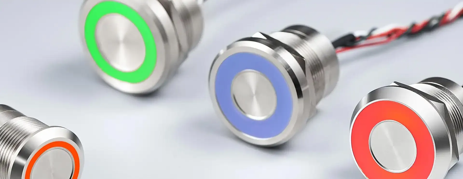
    This guide explains, in straightforward language, how to wire a 3 pins push button switch. It’s written so even beginners can follow the steps. For push button switch wholesale options, contact Langir for further details. Langir makes high-quality switches, and this guide reflects years of hands-on know-how. We’ll break down switch functionality, discuss safety preparations, show wiring diagram tips, walk through step-by-step instructions, explore useful applications, and wrap up common troubleshooting tips. Let’s dive in and learn exactly how to make your switch work just right.


    3 Pin Push Button Switch Functionality

    The very first thing you need to know is what each pin on the switch does. A 3 pin push button switch has three crucial terminals that control its behavior. Understanding them makes wiring easier, prevents errors, and ensures your circuit works correctly.


    3 Pin Push Button Switch Functionality

    Contact Langir for Custom Push Button Switches


    Common COM Terminal on the Switch

    The common terminal, or COM, is the central pin that often carries the make-or-break connection when the button is pressed. It’s the reference point from which the other two operate. In many applications, the COM pin provides the source voltage that the switch directs to the load when activated.


    The Role of the Normally Open NO Terminal

    The Normally Open (NO) terminal doesn’t have a connection with the COM until you push the button. When released, no current flows between COM and NO. This setup is ideal for circuits that only need to be active momentarily, like starting a motor or triggering a relay.


    The Function of the Normally Closed NC Terminal

    In contrast, the Normally Closed (NC) terminal is connected to COM by default. Once the push button is pressed, the connection is broken, stopping the current flow. This polarity is useful where you need a circuit to be active at all times until interrupted.


    Distinguishing 3 Pin Push Buttons From Other Switch Varieties

    Unlike toggle or rocker switches, a 3 pin push button is designed for momentary action. Its compact design and precise functionality make it perfect for electronics that require quick, temporary activations. Recognizing these differences helps you choose the best switch for your project.


    Essential Preparations to Wire a 3 Prong Switch Safely

    Before you start wiring your switch, take the time to get prepared. Safety and proper planning ensure that you don’t make mistakes that could harm your equipment—or yourself.


    Essential Preparations to Wire a 3 Prong Switch Safely

    Contact Langir for Custom Push Button Switches


    Gathering the Correct Tools and Materials for the Job

    First, collect all the necessary tools and materials. You’ll typically need a screwdriver, wire stripper, multimeter, soldering iron, and a set of wires. It’s also a good idea to have a wiring diagram for reference. Using the right tools minimizes hassle and mistakes.


    Key Safety Measures Before Beginning Your Wiring Project

    Safety comes first. Always disconnect the power supply before touching any wiring. Use insulated tools and wear safety goggles. Following these precautions helps prevent electric shocks or short circuits while working on your circuit.


    Fundamental Electrical Concepts for Switch Installation

    Know the basics—voltage, current, resistance, and grounding. A push button switch is part of a larger circuit, so understanding how current flows can help troubleshoot issues if things don’t work as expected. Basic concepts like Ohm’s law will let you verify connections with a multimeter.


    Push Button Switch Wiring Diagram Guide

    Diagrams are a practical tool to visualize how your push button switch works within the circuit. Review the schematic carefully before starting your work, as it shows the current path and connections between the pins.


    Push Button Switch Wiring Diagram Guide

    Contact Langir for Custom Push Button Switches


    Interpreting Standard Schematics for a 3 Pin Switch

    A typical schematic shows the COM line, and then it branches to the NO and NC pins. The diagram will indicate which wire should go where. With a clear schematic, you can confidently wire the switch according to design.


    Visualizing Current Path in a Push Button Circuit

    Picture how the current flows: when the button is not pressed, it flows from COM to NC, but pressing the button diverts it from COM to NO. This visualization helps you organize where each connection should be made, reducing the chances of wiring errors.


    Illustrative Diagrams for Popular Wiring Setups

    Look up simple diagrams online to see different setups. For instance, one diagram may show the switch used to control an LED lamp. Visual aids reinforce your understanding and guide your wiring process.


    Step-by-Step Instructions for How to Wire a 3 Pin Switch

    Let’s walk through the wiring process together. Following these steps should lead to a reliable connection. Patience and careful work go a long way in getting your switch wired perfectly.


    Step-by-Step Instructions for How to Wire a 3 Pin Switch

    Contact Langir for Custom Push Button Switches


    Preparing Wires to Ensure Secure Connections

    Start by stripping your wires to expose sufficient copper, but not too much. Twist them neatly to avoid stray strands. Clean ends ensure that your connections are solid, reducing resistance and heat buildup.


    Making the Connection to the Common Terminal

    Attach the common (COM) wire first. Secure it to the designated terminal using either solder or a connector, depending on your switch design. Ensure the connection is firm; a loose wire can cause intermittent operation.


    Wiring Your Switch for Normally Open NO Operation

    Next, connect the wire that goes to the load or circuit component from the NO terminal. Because the NO pin is disconnected until pressed, this connection only activates when needed. Double-check that your insulation is intact to avoid accidental shorts.


    Wiring Your Switch for Normally Closed NC Operation

    Wire the NC terminal by connecting it to the appropriate part of your circuit that should be active until the button is pressed. This setup is reversed from the NO wiring, so careful attention to your schematic is essential.


    Verifying Your Newly Wired Push Button Switch

    Finally, use a multimeter to test the continuity between COM and the other terminals. Press the button and verify that connections break or form as expected. This step confirms that the wiring is correct before reapplying power.


    Exploring Applications for a Three Way Push Button Switch Configuration

    A 3 pin push button switch isn’t just for simple circuits. It opens up a range of creative and practical applications in various electronic projects.


    Exploring Applications for a Three Way Push Button Switch Configuration

    Contact Langir for Custom Push Button Switches


    Implementing Momentary ON Control Using a 3 Pin Switch

    In many projects, you need a brief “on” signal. Wiring the switch to trigger a relay can momentarily power a device, such as an actuator or a warning light. This setup suits systems that require a quick response.


    Establishing Momentary OFF Control Mechanisms

    Similarly, you can use the switch to immediately cut off power. Using the NC terminal, the switch remains engaged (on) until it is pushed to disconnect. This configuration is ideal for emergency stop buttons in machinery.


    Using Your 3 Prong Switch in Basic Electronic Projects

    From DIY doorbells to test circuits on a breadboard, the versatile design of the 3 pin push button switch fits numerous projects. Its functionality makes it a favorite for hobbyists and professionals alike, ensuring reliable operation in various scenarios.


    Simple Circuit Ideas for Your Push Button

    Consider an LED indicator circuit where the push button temporarily lights up the LED. Or, get creative with an Arduino project to switch motors on and off. Such straightforward ideas demonstrate the switch’s practical usability in everyday electronic designs.


    Addressing Common Issues When You Wire a 3 Pins Push Button Switch

    Even when you follow instructions, issues can happen. Troubleshooting is part of the process; knowing what to look for saves time and effort.


    Contact Langir for Custom Push Button Switches

    Contact Langir for Custom Push Button Switches


    What to Check if Your Switch Fails to Operate

    If the switch doesn’t work, first check your connections. Look for loose wires, improper solder joints, or incorrect wiring order. A quick continuity test with a multimeter helps pinpoint the issue.


    Identifying and Rectifying Frequent Wiring Mistakes

    Common mistakes include connecting the wrong wires to the NO or NC terminals. Always refer back to your diagram. Correcting these wiring errors usually restores proper functionality without further complications.


    Ensuring Durable and Reliable Connections

    For long-term reliability, secure all connections tightly. Use heat shrink tubing or electrical tape to insulate exposed wires properly. These precautions help in preserving connection integrity over time, especially in vibrating or high-temperature conditions.


    Knowing When to Get Help With Your Wiring Task

    If problems persist after troubleshooting, it may be time to consult an expert or revisit your wiring diagram. Sometimes a fresh pair of eyes helps you catch subtle mistakes that you might overlook.


    How to Wire a 3 Pins Push Button Switch | FAQs

    What makes a 3 pin push button switch different from other switches?

    It features a COM, NO, and NC terminal, allowing momentary activation or deactivation, unlike toggle switches that maintain state. This flexibility makes it ideal for specific applications like safety circuits.

    How do I test if my wiring is correct?

    Use a multimeter to check continuity between the COM terminal and the NO or NC terminals while pressing the button. Correct changes in continuity indicate proper wiring.

    What safety precautions should I take when wiring?

    Always disconnect power, use insulated tools, and follow proper electrical safety measures. Ensuring a safe work environment is key to preventing shocks or circuit damage.

    Can I use this switch in high-voltage applications?

    Generally, these switches are ideal for low-voltage circuits. Always refer to the switch’s specifications and guidelines from Langir to ensure safe usage in your design.

    What if my switch does not work after wiring?

    Double-check all connections, verify wiring according to the diagram, and test each terminal with a multimeter. If issues persist, consider consulting an expert for further troubleshooting.


    [/vc_column_text][/vc_column][/vc_row][vc_row][vc_column][vc_zigzag]

    Get Custom Quote
    We’ll get back to you within 12 hours.
    Drag & Drop Files, Choose Files to Upload You can upload up to 3 files.
    [/vc_column][/vc_row][vc_row][vc_column][vc_zigzag][/vc_column][/vc_row]

  • How to Wire Car Push Button With Led

    How to Wire Car Push Button With Led

    [vc_row][vc_column][vc_column_text css=””]


    Wiring a car push button with LED might sound like rocket science, but it’s actually pretty straightforward—if you know what you’re doing. For those considering car push button wholesale purchases, this guide is a great place to start. Langir, a trusted Chinese manufacturer with 16 years in piezo switches, has seen it all. In fact, if you ever need to contact Langir for more information, they are just a call away. Today, we’re breaking down the wiring process, explaining every step in everyday language. You’ll learn about terminal connections, LED circuits, proper wire gauges, and even how to integrate everything onto your dashboard. Let’s get you set up with a reliable, durable push button switch that not only works great but lights up nicely. Ready to dive in?


    Car Push Button With Led Components

    This section covers the basics. When wiring a push button switch, you’ve got a few key parts to deal with. First off, there are the terminals where you connect your wires. Then, there’s the LED circuit itself that gives you that cool glow. And don’t forget about selecting the right wire gauges to handle the power without risking shorts or voltage drops.


    Car Push Button With Led Components

    Contact Langir for Custom Car Push Buttons with LED


    Terminals on Automotive Push Button Switches

    The terminals are the connection points on the switch. Think of them as the entry and exit doors for electricity. When wiring your car push button switch, each terminal has a specific role—input, output, and ground. Always check your switch diagram to know which terminal does what. A loose connection here isn’t just annoying—it can mean your switch fails mid-trip, and let’s face it, your car engine start button should never play hide-and-seek with your power.


    LED Circuit Within the Car Push Button Switch

    The LED circuit is what lights up your button. It’s built to provide the right voltage and current, ensuring that your LED not only turns on but shines consistently. This mini-circuit often includes resistors and sometimes even diodes to keep things safe. This part of the design is critical if you want that crisp, bright LED that guides you even on dark nights. Make sure the wiring for the LED is done according to the manufacturer’s specs so you avoid those pesky burnouts.


    Selecting Appropriate Wire Gauges for Your Project

    Choosing the right wire gauge is like selecting the right size of fuel tank: too small, and you get overheating or voltage drops; too big, and well, you’re just wasting money (and space). Generally, 18–20 AWG wires are common, but if you’re running longer distances, consider a thicker gauge. Always match the wire size to your expected amperage. This ensures a solid, reliable connection and keeps your circuit safe from shorts and power drops.


    Tools and Materials for Wiring a Car Push Button Switch

    Before you roll up your sleeves, gather your tools and materials. Having the right equipment makes the process smooth and helps you avoid frustrating setbacks.


    Tools and Materials for Wiring a Car Push Button Switch

    Contact Langir for Custom Car Push Buttons with LED


    Essential Hand Tools for Electrical Wiring

    You’ll need a good set of basic tools: wire strippers, crimpers, small screwdrivers, and maybe even a multimeter. A multimeter is essential for checking voltage and continuity. With a few simple instruments in hand, you can double-check every connection and ensure nothing’s out of place.


    Required Connectors and Terminals

    Connectors and terminals are the unsung heroes. Make sure you have terminal blocks or solder connectors suited to automotive use. These secure your wires firmly and offer protection against vibrations and wear. High-quality connectors not only ensure better performance—they last longer, which is key when you’re dealing with components in a moving vehicle.


    Sourcing a Suitable Automotive Push Button Switch With LED

    While there are countless options out there, look for one that meets your specific needs. Langir offers highly reliable, customizable push button switches at wholesale rates. When choosing, verify that the switch’s specifications match your project requirements, from voltage ratings to current capacity. This switch is the centerpiece of your setup, so quality matters.


    Obtaining Fuses and Fuse Holders for Circuit Protection

    Fuses are your circuit’s safety net. They prevent dangerous overcurrent situations that could fry your wiring. Pick a fuse holder that fits well within your dashboard layout and choose a fuse rated appropriately for your switch’s load. A solid fuse setup can save you a lot of heartache down the road, ensuring that your car’s push button switch is protected from any unforeseen surges.


    Step-by-Step Guide to Wiring Your Car Push Button with Led

    Time to get your hands dirty with the wiring. Follow these instructions to ensure a proper setup that works reliably every time.


    Step-by-Step Guide to Wiring Your Car Push Button with Led

    Contact Langir for Custom Car Push Buttons with LED


    Safely Disconnecting the Vehicle’s Battery

    Safety first! Before you start, disconnect the battery to avoid accidental shorts or shocks. This step can’t be overlooked. A quick disconnection ensures that you won’t end up with sparks flying or damage to your car’s electrical system.


    Connecting the Power Source to the Car Push Button Switch

    Now reconnect only the power source wiring. Match the positive lead to the input terminal, and verify with your multimeter that the correct voltage is present. Proper connections here mean that your entire circuit will function without hiccups. Keep your wiring neat and avoid crimping any cables to ensure a stable connection.


    Wiring the LED Terminals for Illumination

    Next, wire the LED terminals. Connect the resistor in series as required by your LED specs. This step safeguards your LED from too much current and ensures it glows with just the right brightness. Double-check polarity so your LED lights up without any flickers.


    Connecting the Output Terminal to the Intended Accessory

    Once your power and LED are set, wire the output terminal to whatever accessory you want to control. This might be an engine start circuit, dashboard light, or even another accessory like a motor relay. Secure these connections firmly to maintain a steady signal when the button is pressed.


    Grounding Your Car Push Button With Led Correctly

    Finally, establish a solid ground. Grounding stabilizes your circuit and helps manage interference and noise. Use a clean, unpainted metal surface for the ground connection to avoid any potential issues. Remember, a secure ground means reliable operation every time your switch is activated.


    Integrating Your Automotive Push Button Switch Into the Dashboard

    Integrating your new switch into your car’s dashboard is all about secure mounting and tidy wiring. This is where form meets function.


    Integrating Your Automotive Push Button Switch Into the Dashboard

    Contact Langir for Custom Car Push Buttons with LED


    Choosing a Mounting Location for the Car Push Button Switch

    Pick an easily accessible spot on your dashboard. You want the button to be reachable but not in the way. Consider comfort and emergency accessibility because if your car engine start button or alarm system feels clunky, it could lead to mishaps.


    Drilling the Mounting Hole Accurately

    When it’s time to drill, measure twice, drill once. A precise hole ensures a clean installation and a professional look. Use a drill bit that matches the switch size; too big, and it may wiggle; too small, and you might damage the switch housing.


    Securing the Push Button Switch for a Stable Fit

    With the hole ready, use the provided screws or fasteners to mount the switch securely. A stable mount prevents vibrations from loosening connections. Tighten carefully—you want it firm, but be careful not to overtighten, which might crack the button or its LED housing.


    Routing Wires Neatly and Safely

    Finally, route the wires so they’re not tangled or pinched. Use zip ties or adhesive clips to secure them. Neat wiring not only improves safety and reliability but also makes future troubleshooting a breeze. Your dashboard will look organized and professional—plus, you’re less likely to encounter annoying shorts.


    Testing Your Newly Wired Car Push Button with Led

    After all that effort, it’s time to test your work. Reconnect the vehicle’s battery, and then check that everything functions as it should.


    Testing Your Newly Wired Car Push Button with Led

    Contact Langir for Custom Car Push Buttons with LED


    Reconnecting the Vehicle’s Battery

    Reconnect the battery carefully. Ensure all connections are secure before powering up. This step re-energizes your circuit and prepares you for the ultimate test.


    Verifying LED Illumination on the Car Push Button Switch

    Press the button to check the LED. The light should come on without flickering, a good sign that your LED circuit is working correctly. If it doesn’t light, recheck your resistor values and wiring polarity.


    Confirming the Switched Accessory Operates as Expected

    Activate the switch and observe the connected accessory. Whether it’s an engine start button or another feature, a smooth operation means you’re in business. Any glitches here mean it’s time to dive back in and double-check your terminal connections.


    Checking All Connections for Security and Safety

    Lastly, inspect every connection. Wiggle the wires to ensure nothing is loose. This final check is crucial to ensure safety and longevity. A tight, secure circuit makes for reliable performance every time you press that button.


    Troubleshooting Common Automotive Push Button Switches Wiring Issues

    Even when you follow the steps, hiccups can occur. Let’s troubleshoot some common issues so you’re ready to fix them on the fly.


    Troubleshooting Common Automotive Push Button Switches Wiring Issues

    Contact Langir for Custom Car Push Buttons with LED


    Addressing a Non-Illuminating LED on Your Car Push Button With Led

    If your LED isn’t lighting up, consider a few things: check the resistor value, verify the LED polarity, and ensure the power supply is ample. Sometimes, a faulty connection or a weak battery can be the culprit.


    What to Do When the Switch Does Not Activate the Accessory

    If pressing the switch doesn’t trigger the accessory, inspect the output terminal connection. Verify with a multimeter that the voltage is reaching the accessory. A loose wire or a mistaken terminal assignment might be to blame.


    Resolving Intermittent Operation of Your Car Push Button Switch

    Intermittent operation often points to a loose connection or a degraded wire. Check every connection and ensure that crimping is done properly. Re-solder or re-crimp if necessary, and keep those wires secure.


    Identifying and Fixing Short Circuits or Blown Fuses

    If a fuse blows or there’s a short, retrace your wiring. Look for exposed wires or frayed insulation that might be causing contact. Replace any blown fuses with the correct rating, and ensure that all connections are firmly insulated.


    How to Wire Car Push Button With Led | FAQs

    What basic tools do I need for wiring a car push button switch?

    You’ll need wire strippers, crimpers, a screwdriver, and a multimeter. These tools help ensure every connection is secure and that your voltage levels are correct.

    How do I choose the right wire gauge for my project?

    Wire gauge selection depends on current requirements. Generally, 18–20 AWG works for most applications, but longer runs might require thicker wires for stability.

    What if my LED doesn’t light up after wiring?

    Double-check your resistor value, wiring polarity, and connections. Verify that the power supply is sufficient, and inspect for any loose wires.

    Can I install the switch myself without professional help?

    Yes, if you’re comfortable with basic wiring and follow safety protocols like disconnecting the battery, you can do it yourself.

    How do I prevent shorts and blown fuses?

    Use proper connectors, secure all wires with zip ties, and install the correct fuse rating for your circuit. This setup ensures a safe, reliable installation.


    [/vc_column_text][/vc_column][/vc_row][vc_row][vc_column][vc_zigzag]

    Get Custom Quote
    We’ll get back to you within 12 hours.
    Drag & Drop Files, Choose Files to Upload You can upload up to 3 files.
    [/vc_column][/vc_row][vc_row][vc_column][vc_zigzag][/vc_column][/vc_row]

  • How to Wire a 2 Pin Switch | Mastering the Basics

    How to Wire a 2 Pin Switch | Mastering the Basics

    [vc_row][vc_column][vc_column_text css=””]


    This guide explains how to wire a 2 pin switch in a straightforward, down-to-earth style. For those interested in bulk purchasing options, exploring a 2 pin switch wholesale solution can be very beneficial. It covers the switch’s function, the tools you need, step-by-step wiring instructions for both push button and toggle styles, and how to test your job. Langir, a trusted manufacturer with 16 years in piezo switches, knows that quality wiring isn’t just about connections—it’s about safe, reliable, and efficient performance in industrial settings. For further assistance or expert advice, please do not hesitate to contact Langir.


    2 Pin Switch and Its Function

    A 2 pin switch controls the flow of electricity by opening or closing a circuit with just two connection points. Its primary function is simple—allowing or interrupting current—with applications in everything from industrial control panels to board-level electronics.


    2 Pin Switch and Its Function

    Contact Langir for Custom Push Button Switches


    Terminals on a Basic 2 Pin Switch

    The switch has two clean metal pins serving as terminals. One connects to the power source while the other links to the load. Each terminal is made of robust materials such as brass or steel for longevity and reliable contact, helping minimize resistance and voltage drop.


    Common Applications for Two Prong Switches

    Industrial machinery, consumer electronics, and lighting systems all use these switches. They help control motors, relays, and even simple indicator circuits. Their streamlined design makes them ideal for low-voltage and quick-access scenarios.


    Differences Between Normally Open and Normally Closed 2 Pin Switches

    Normally open switches only complete the circuit when pressed, while normally closed ones conduct until action stops the current. This distinction is crucial. For instance, in emergency stop circuits, a normally closed switch is preferred to cut off power immediately.


    Safety Precautions Before Starting Any 2 Pin Switch Wiring

    Always disconnect power before starting. Using a multimeter ensures no live current, helping prevent shocks or shorts. Wear insulated gloves and tools like a screwdriver to support safety during installation.


    Essential Tools and Materials for Wiring

    Wiring a 2 pin switch requires the right tools and materials. Using the correct wire gauge is key to handling current safely.


    Essential Tools and Materials for Wiring

    Contact Langir for Custom Push Button Switches


    Selecting the Correct Wire Gauge for Your 2 Pin Switch

    Wire gauge must match the expected load. Thicker wires reduce energy loss and are crucial for heavy-duty applications. Consult a gauge chart for specific ratings.


    Necessary Hand Tools for a Clean Installation

    A reliable screwdriver, wire stripper, and crimping tool are essential. These help create clean cuts and secure connections, ensuring your wiring stays safe under vibration or movement.


    Choosing a Suitable 2 Pin Rocker Switch or Toggle Type

    Pick a switch that matches your application—a rocker switch may be more ergonomic, while a toggle offers a traditional feel. Consider factors like durability and aesthetic appeal.


    Acquiring Wire Connectors and Insulating Materials

    Use quality wire connectors, heat shrink, or insulating tape to secure exposed connections. These accessories prevent accidental shorts and enhance the longevity of the installation.


    Preparing the Wires for a Two Prong Toggle Switch Connection

    Preparation is key. Begin by stripping the insulation from wire ends and twisting stranded wires to form a neat bundle.


    Preparing the Wires for a Two Prong Toggle Switch Connection

    Contact Langir for Custom Push Button Switches


    Safely Stripping Wire Insulation

    Use a wire stripper carefully to expose just enough conductor without nicking the metal. This ensures a healthy connection is made with the switch terminal.


    Twisting Stranded Wires for Secure Terminal Contact

    Twist the exposed copper strands uniformly. A tight twist helps produce a robust and reliable connection that resists loosening over time.


    Checking for Power With a Multimeter Before Wiring

    Always confirm that no power is running through the wires using a multimeter. This prevents unexpected shocks and ensures a safe setup.


    Planning Your Wire Routing for a Neat Setup

    Lay out the wiring path before connecting. Secure wires with clips or ties. A clean setup not only looks professional but minimizes interference in circuits.


    Step-by-Step Wiring for a 2 Pin Push Button Switch

    Follow a diagram specific to your push button switch model. This hands-on approach guarantees that every connection is intentional and safe.


    Step-by-Step Wiring for a 2 Pin Push Button Switch

    Contact Langir for Custom Push Button Switches


    Consulting Your 2 Pin Push Button Switch Wiring Diagram

    Always start by reading the diagram provided by Langir. It details correct placement of each cable to avoid mix-ups during installation.


    Connecting the Power Source Wire to the First Terminal

    Secure the power source wire firmly to the first terminal. A clean screw terminal connection ensures low resistance and efficient current flow through the switch.


    Attaching the Load Wire to the Second Terminal

    Next, attach the load wire that carries the output signal to your device. Ensure this connection is equally secure to maintain uninterrupted flow when the switch is activated.


    Securing the Connections on Your 2 Pin Push Button Switch

    Double-check all screws and connectors. A loose connection might cause intermittent failures or energy loss.


    Mounting the Push Button Switch in Its Housing

    Fasten the push button switch into its designated panel or enclosure. Use the provided mounting hardware, ensuring the switch sits flush and won’t vibrate loose.


    Executing the Wiring for a Toggle Switch With 2 Prongs

    Toggle switches with 2 prongs are wired similarly but follow a unique configuration to match their design. This method is ideal for applications needing a more tactile feel.


    Executing the Wiring for a Toggle Switch With 2 Prongs

    Contact Langir for Custom Push Button Switches


    Identifying the Input and Output Prongs on the Toggle Switch

    Look at the toggle switch markings carefully. One prong receives power while the other delivers it to the load, and misidentification can halt the circuit.


    Connecting the Hot Wire to the Input Prong

    Attach the hot wire to the designated input prong. Using a screwdriver, tighten the terminal securely to avoid any slack in the connection.


    Running the Switched Wire From the Output Prong to the Device

    Connect the switched wire to the output prong leading to your device. A direct, clean connection ensures minimal transmission loss.


    Ensuring Tight Connections for a Reliable Two Prong Toggle Switch Operation

    Perform a brief visual and physical inspection. Each terminal should be tight, the wires well-insulated, and the overall wiring layout neat. This is crucial for both operational efficiency and safety.


    Testing and Finalizing Your 2 Pin Rocker Switch Installation

    After wiring, testing validates your work. Power up gradually to safely check circuit operation without surprise disruptions.


    Testing and Finalizing Your 2 Pin Rocker Switch Installation

    Contact Langir for Custom Push Button Switches


    Performing a Continuity Test on Your 2 Pin Rocker Switch Wiring

    Use a multimeter for a continuity test. This confirms that electrical connectivity is correct between the intended terminals and that there are no shorts.


    Safely Restoring Power to Test the Circuit

    Once tests pass, slowly reconnect power. Monitor for any flicker or abnormal behavior, indicating a possible wiring error needing correction.


    Observing the 2 Pin Rocker Switch Operation

    Operate the switch several times to check responsiveness. A good switch will show immediate reaction to each input, with no lag or inconsistent contact.


    Troubleshooting Common Issues With 2 Pin Switch Connections

    If issues arise, recheck all terminal connections. Loose wiring, insufficient stripping, or misconnected wires are common errors. Reevaluate the wiring diagram for any missed steps.


    Insulating All Exposed Wires and Terminals Securely

    Finalize your job by insulating all exposed wires with heat shrink tubing or electrical tape. This extra step prevents accidental shorts and protects the wiring over time.


    Essential Tools and Materials for Wiring


    Tool/Material Purpose Recommended Type Benefit
    Wire Stripper Removing insulation from wires Precision stripper Prevents damage to conductors
    Screwdriver Tightening terminal screws Insulated flat-head Ensures a secure connection
    Multimeter Testing for live current and continuity Digital multimeter Verifies safe, correct wiring
    Crimping Tool Securing connectors Ratcheting crimper Provides durable, stable connections
    Insulating Tape/Heat Shrink Tubing Covering exposed wires Quality electrical tape Enhances safety and longevity in installations

    The above table summarizes the key materials and their roles. Using high-quality tools guarantees a reliable connection and extends the life of your installation.


    How to Wire a 2 Pin Switch | FAQs

    Why is it important to check for power with a multimeter before wiring? Always check with a multimeter to ensure no current flows through the wires. This precaution prevents shocks and accidental short circuits during installation.

    How do I choose the right wire gauge for my 2 pin switch? Refer to a wire gauge chart. The gauge must suit your circuit’s current requirements to ensure minimal energy loss and a safe connection.

    What is the difference between a normally open and normally closed 2 pin switch? A normally open switch breaks the circuit until pressed, while a normally closed switch keeps the circuit closed until activated. Your application determines which type you need.

    How can I ensure my connections on the switch stay secure over time? Use proper tools, make clean connections with stripped wires, and secure them firmly. Insulating exposed terminals with heat shrink tubing or tape further enhances durability.

    What troubleshooting steps are recommended if the switch does not work properly? Recheck every connection, verify using a multimeter for continuity, and ensure no wires are loose or misconnected. Often, a re-inspection solves the common errors.


    [/vc_column_text][/vc_column][/vc_row][vc_row][vc_column][vc_zigzag]

    Get Custom Quote
    We’ll get back to you within 12 hours.
    Drag & Drop Files, Choose Files to Upload You can upload up to 3 files.
    [/vc_column][/vc_row][vc_row][vc_column][vc_zigzag][/vc_column][/vc_row]

  • How to Wire a 4-Pin Illuminated Push Button Switch

    How to Wire a 4-Pin Illuminated Push Button Switch

    [vc_row][vc_column][vc_column_text css=””]


    This handy guide focuses on how to wire an illuminated push button switch, specifically the 4-pin variety. For those who may not be familiar, an illuminated push button switch is a simple yet effective component typically used to add a visual element to your gadgets and projects. To get started, you’ll need a few tools: wire strippers, a soldering iron (if you’re feeling adventurous), and some stranded wire. Make sure to grab your switch and review its pin layout, which usually consists of two pins for power and two for the illumination feature.

    These are generally labeled on the switch itself or in the accompanying documentation. One pin connects to the positive terminal of your power source, while the other pin connects to the device you’re controlling. The illumination feature usually requires a separate connection to your power source, specifically to ensure the light turns on when the button is activated. For this, connect one of the illumination pins to the positive side of your power, and the other to ground. Once everything is snugly wired, give yourself a moment to admire your handiwork and then test the switch. With any luck, the button will light up like a tiny beacon of hope, making all your hard work worth it.


    Illuminated Push Button Switch and Its 4 Pins

    This section explains the basics of an illuminated push button switch with a 4-pin configuration. It is widely available through illuminated push button switch wholesale channels that cater to diverse applications. In simple terms, the switch has four distinct terminals that serve different functions. One terminal connects to the power, one to the load, another acts as ground, and the last one drives the LED illumination. This means every pin has a role in making sure your switch not only controls a circuit but also lights up to signal its status. For additional support, feel free to contact Langir.


    Illuminated Push Button Switch and Its 4 Pins

    Contact Langir for Custom Illuminated Push Button Switches


    The Power, Ground, Load, and LED Terminals on a 4 Pin Switch

    The power terminal brings the supply voltage into the switch, while the ground terminal completes the circuit. The load terminal directs the current to the device being controlled, and the LED terminal is dedicated to lighting the button. Each connection creates a specific pathway, ensuring that the circuit operates safely and efficiently. This clear pinout makes troubleshooting straightforward, even for beginners.


    Normally Open and Normally Closed Functions in Your Switch

    Push button switches can work as normally open (NO) or normally closed (NC). In a normally open configuration, the circuit remains incomplete until the button is pressed, allowing current to flow only momentarily. Conversely, with a normally closed setup, the circuit is completed by default and the press creates a temporary break in the flow of electricity. Understanding these differences is vital for incorporating the right switch type into your project.


    Common Types of Illuminated Push Button Switches Available

    There are several common types available in the market. For example: 1. Panel Mount Push Buttons – Often used in control panels where durability and ease of access are needed. 2. Surface Mount Push Buttons – Ideal for compact devices and circuit boards where space is limited. 3. Waterproof Push Buttons – Designed for outdoor or industrial applications with protection against water and dust. Each variant is designed to provide reliable performance while ensuring that the LED remains bright even under different electrical conditions.


    How the Internal LED Circuit Operates Within a 4 Pin Design

    Inside these switches, a small LED circuit works to indicate whether the switch is activated. When power flows through the appropriate LED pin, a resistor limits the current to a safe level, protecting the LED from burning out. This simple yet effective design ensures a prolonged lifespan and helps prevent common issues such as flickering.


    Key Electrical Ratings to Verify for Your 4 Pin Switch Wiring Project

    Before wiring your switch, check electrical ratings like voltage, current capacity, and power dissipation. Matching your switch with the right ratings is crucial to avoid issues like voltage drop or short circuits. Using the correct wiring gauge and ensuring proper insulation are also essential steps to guarantee safe operation.


    Essential Tools and Safety Measures

    Working with electrical components means you need the right tools and a safe workspace. Gather quality screwdrivers, a soldering iron, wire strippers, and a multimeter. These tools are essential for measuring and confirming the integrity of each connection.


    Essential Tools and Safety Measures

    Contact Langir for Custom Illuminated Push Button Switches


    Gathering the Necessary Wiring Implements and Connectors

    Reliable wires, terminal connectors, and heat shrink tubing are necessary for a neat jobs. Using the right type of connectors ensures stable and lasting connections, eliminating the risk of loose terminals that might lead to shorts or malfunctions.


    Selecting Suitable Wires for Your Illuminated Push Button Switch Setup

    Make sure to choose wires that can carry the expected current without overheating. Wires with proper insulation and gauge prevent issues like voltage drop and interference, ensuring the entire circuit remains stable and efficient.


    Observing Fundamental Electrical Safety Guidelines During Installation

    Always disconnect power before starting any wiring work. Wear safety glasses, avoid touching live circuits, and make sure your work area is dry and non-conductive. These precautions help prevent accidents like shocks or fires while ensuring safe and professional results.


    Preparing Your Work Area for a Secure Wiring Procedure

    A clean, organized workspace reduces mishaps during installation. Set up an anti-static mat, clearly mark wire lengths, and secure all tools nearby so there are no sudden interruptions during the wiring process.


    Understanding Voltage and Amperage for Your Illuminated Switch

    Knowing the voltage and current requirements for both the LED and the switch is critical. This prevents miswiring that could result in component failure. A multimeter can verify that each connection meets the expected levels, giving you confidence in your installation.


    Decoding the 4 Pin Push Button Switch Wiring Diagram

    Understanding wiring diagrams can feel like learning a new language—but it’s all about reading the symbols. The diagram for a 4-pin switch shows each pin’s function and interconnection with the overall circuit.


    Contact Langir for Custom Illuminated Push Button Switches

    Contact Langir for Custom Illuminated Push Button Switches


    Interpreting Standard Symbols in a 4 Pin Push Button Switch Wiring Diagram

    In diagrams, symbols represent power sources, grounds, loads, and LEDs. Each symbol is standardized so that you can easily match them with actual terminals on your switch. The power symbol, for instance, typically looks like a plus sign, while ground is represented by multiple descending lines.


    Matching Diagram Terminals to Your Actual Illuminated Push Button Switch

    Once you understand the symbols, compare them with the physical switch. Ensure each terminal on the switch corresponds correctly to the diagram. This visual matching minimizes errors and ensures the wiring will operate as intended.


    Recognizing Various Illumination Wiring Approaches in Schematics

    Different diagrams might show alternate methods for integrating the LED. Some use resistors within the circuit explicitly, while others integrate them internally. Knowing these differences lets you adapt the wiring to suit your available components and desired lighting effect.


    Finding Accurate Wiring Diagrams for Your Specific Switch Type

    Always refer to the manufacturer’s schematic provided with your switch. These diagrams offer the most reliable guidance and keep your project in line with industry standards. Cross-reference any online diagrams with the product manual for extra security.


    Typical Errors to Sidestep When Reading a 4 Pin Switch Wiring Diagram

    Common mistakes include misidentifying the load terminal or skipping the insulation requirements for high-voltage connections. Double-check each connection with a multimeter and verify that every symbol aligns with an actual pin on your switch.


    Step-by-Step Guide to Wire Your Illuminated Push Button Switch

    Here’s a clear guide to help you wire your switch confidently. Follow these steps closely for a reliable setup.


    Step-by-Step Guide to Wire Your Illuminated Push Button Switch

    Contact Langir for Custom Illuminated Push Button Switches


    Preparing Wire Ends for Connection to the 4 Pin Switch

    Strip the wires to the correct length—enough to fit securely into the terminals without leaving excess exposed copper. A proper cut ensures tight connections and minimizes the risk of short circuits.


    Connecting the Input Power Source to the Illuminated Push Button Switch

    Attach the power wire to the designated terminal. Ensure that the connection is firm, using either screw terminals or soldered joints. This connection brings the required voltage into the circuit and is vital for overall operation.


    Wiring the Device or Circuit to Your 4 Pin Push Button Switch Output

    Connect the output wire from the load side of your switch to the device you plan to control. This wiring completes the circuit when the button is pressed. Make sure every connection is secure and that there is proper insulation around each terminal.


    Completing the Connections for the Switch’s LED Illumination

    Wire the LED terminal in line with the circuit so that when the switch is activated, the LED lights up. Use a resistor inline if it’s not incorporated internally to limit current and protect the LED.


    Ensuring All 4 Pin Switch Wiring Connections Are Secure and Insulated

    Once wired, check every connection with a multimeter. Wrap or insulate each terminal with electrical tape or heat shrink tubing to prevent accidental shorts. This extra step ensures long-term reliability and safety.


    Common Wiring Configurations for an Illuminated Push Button Switch

    Different wiring setups can change how your switch and LED behave. Below are some typical configurations you might use for various applications.


    Common Wiring Configurations for an Illuminated Push Button Switch

    Contact Langir for Custom Illuminated Push Button Switches


    Wiring the LED to Activate When the Switch Is Engaged

    In this configuration, the LED lights only when the button is pressed. This setup visually signals when the circuit is closed and the device is activated, making it clear for users.


    Establishing Constant LED Illumination Regardless of Switch Position

    Sometimes the LED may need to be on constantly to indicate power presence. This wiring approach bypasses the switch in the LED circuit so that the indicator remains lit regardless of the switch state.


    Implementing 4 Pin Switch Wiring for a Momentary Operation

    Some applications require the switch to work momentarily—activating a device only as long as the button is held. This momentary configuration often utilizes a normally open setup that returns to the off state immediately after release.


    Configuring a Latching Function With Your Illuminated Push Button Switch

    Latching wiring keeps the circuit closed until an external reset occurs. This is perfect for applications where you want the button to toggle between states without continuous pressure.


    Adjusting Wiring for Different LED Voltage Requirements in Your Switch

    Ensure you adjust resistors and wiring paths if using an LED that requires a different voltage. This careful adjustment prevents voltage mismatch issues and guarantees optimal illumination and function.


    Testing and Troubleshooting Your 4 Pin Switch Wiring Connections

    After wiring, it’s crucial to test your work properly. Start by verifying all connections are secure. Use a multimeter to check that the voltage is reaching the correct terminals and that the LED lights as expected when the button is pressed.


    Testing and Troubleshooting Your 4 Pin Switch Wiring Connections

    Contact Langir for Custom Illuminated Push Button Switches


    Performing Initial Safety Verifications Before Applying Power

    Before you power up the circuit, double-check all connections for proper insulation and verify that the wiring layout matches the provided diagram. This safety step is essential to prevent accidental shorts or heating.


    Methods to Confirm Correct Switch Operation and Illumination

    Apply power briefly while observing the LED and device. If the LED lights when the button is pressed and the device operates correctly, the wiring is successful. If not, re-check each terminal connection carefully.


    Diagnosing Reasons Your Illuminated Push Button Switch LED Fails to Light

    Common causes for LED failure include poor solder joints, misconnected wires, or insufficient resistance. Use a multimeter to trace the voltage drop along the LED circuit and identify any issues.


    Resolving Issues When the Switched Circuit Does Not Function

    If the circuit remains inactive, re-inspect the load and power connections. Verify that the switch itself is functioning and that no pins are cross-connected. Correcting these issues usually fixes the problem swiftly.


    Maintaining the Long-Term Integrity of Your 4 Pin Switch Wiring

    For ongoing reliability, periodically inspect connections for any signs of wear or corrosion. Use high-quality connectors and work in a dry, controlled environment to ensure your wiring stands the test of time.


    How to Wire a 4-Pin Illuminated Push Button Switch | FAQs

    What does each pin on a 4-pin push button switch do?

    One pin supplies power, one acts as the load connector, another is ground, and the last drives the LED for illumination.

    How can I test my switch wiring before full installation?

    Use a multimeter to verify voltage at each terminal and check for continuity, ensuring all connections are secure and properly insulated.

    Why might the LED in my illuminated push button switch not light up?

    Common reasons include miswiring, a missing resistor, poor solder joints, or an incompatible LED voltage requirement.

    Is it safe to wire these switches on my own?

    Yes, if you follow proper safety guidelines—disconnect power, use the right tools, and double-check all connections, you can wire the switch safely.

    What maintenance should I perform on my wiring setup?

    Regularly inspect for corrosion or loose connections, and use high-quality connectors and insulation to ensure long-term reliability.


    [/vc_column_text][/vc_column][/vc_row][vc_row][vc_column][vc_zigzag]

    Get Custom Quote
    We’ll get back to you within 12 hours.
    Drag & Drop Files, Choose Files to Upload You can upload up to 3 files.
    [/vc_column][/vc_row][vc_row][vc_column][vc_zigzag][/vc_column][/vc_row]

  • How to Wire a Push Button Horn Switch | Car & Boat

    How to Wire a Push Button Horn Switch | Car & Boat

    [vc_row][vc_column][vc_column_text css=””]


    This article explains how to wire a push button horn switch for cars and boats. It breaks down every step—from choosing the right wires (if you’re looking for cost-effective parts, consider horn push button wholesale) to troubleshooting common issues. With clear, concise instructions, it helps both DIY enthusiasts and professionals improve safety and functionality without the headache. Each section covers important details, ensuring you know which tools to use and how to avoid errors. For further installation support, feel free to contact Langir. Read on to learn easy wiring techniques and get your horn sounding right every time.


    Essential Preparations for Wiring a Horn Button

    Before you dive in, you need to prepare. Start by assessing your horn system. Knowing which wires to use is key—different horns may come with varied wiring colors and configurations. Next up, select a push button horn switch that fits your vehicle’s or boat’s requirements. Look for one with a durable plastic casing and secure contacts, as this minimizes noise and corrosion.

    Then, gather the necessary tools and safety gear. A decent wire stripper, electrical tape, and a screwdriver will do, along with a multimeter to check voltage. Safety glasses and gloves are a smart choice too. Finally, understand the basic horn circuitry in both cars and boats. Most circuits use a ground wire, a power supply wire, and often include a relay for extra control. This preparation phase sets the stage for a trouble-free installation.


    Essential Preparations for Wiring a Horn Button

    Contact Langir for Custom Push Button Horn Switches


    Identifying the Correct Wires for Your Horn System

    Look closely at your vehicle’s wiring diagram. Identifying the correct wires involves tracing the power source and ensuring proper insulation. Sometimes wires may be hidden under panels; a multimeter helps confirm which one delivers power.


    Selecting a Suitable Push Button Horn Switch

    Not all horn switches are created equal. Choose one built for high frequency use and resistance to weather. The right push button improves reliability and reduces the chance of accidental activation or failure.


    Necessary Tools and Safety Gear for the Installation

    Your toolkit should include a wire stripper, crimping tool, and electrical tape. Safety gear like gloves and goggles protect you during the job. These tools help ensure clean, precise cuts and secure connections.


    Understanding Basic Horn Circuitry in Cars and Boats

    A basic horn circuit generally involves a power positive wire, a ground wire, and a trigger from the push button. In boats, marine-grade wiring and waterproof components are crucial for reliability in wet conditions.


    Step-by-Step Process to Wire a Car Horn Button

    Wiring a car horn button doesn’t need to be complicated. Once the battery is safely disconnected, locate the horn and its existing wiring. This ensures you won’t damage other systems. Follow the wiring diagram specific to your vehicle for accuracy.


    Step-by-Step Process to Wire a Car Horn Button

    Contact Langir for Custom Push Button Horn Switches


    Safely Disconnecting the Vehicle’s Battery

    Always disconnect the battery first; this prevents short circuits and shock hazards. Removing the negative terminal is usually enough to cut power to the circuit.


    Locating the Horn and Its Existing Wiring

    Find the horn under the hood. Typically, it’s mounted near the front grill. Identify the wiring connections and note any existing wiring colors for reference.


    Connecting the New Push Button Switch to the Horn Circuit

    Carefully splice into the existing wires, using connectors and electrical tape. Make sure the push button’s contacts connect to both the power source and the horn. This ensures a reliable trigger when pressed.


    Mounting the Car Horn Button Securely

    Mount the switch in a convenient spot on your dashboard or steering column. Use screws to fasten it and check that the placement won’t interfere with other controls.


    Reconnecting Power and Testing the Car Horn

    Once everything is connected, reconnect the battery. Test the horn by pressing the button to verify that it sounds clearly without intermittent issues. If it fails, recheck every connection.


    Guide to Install a Universal Horn Button

    Universal horn buttons are designed to work on multiple vehicle types, from cars to boats. The kit comes with standard wires and connectors that require minimal adjustments. Before installation, review every component included and match them to your specific application.


    Guide to Install a Universal Horn Button

    Contact Langir for Custom Push Button Horn Switches


    Understanding Universal Horn Button Kit Components

    The kit usually includes a push button, various connectors, a relay, and sometimes a fuse. Each part should be inspected for defects and compatibility. Detailed instructions in the kit guide you through the setup process.


    Adapting Universal Wiring for Your Specific Vehicle or Boat

    Not every vehicle wiring is identical. You may need to extend or shorten wires, using proper crimp connectors to secure them. Check that the wire gauge is compatible with your horn’s power consumption.


    Effective Methods to Install a Universal Horn Button on Various Surfaces

    For different dashboards or panels, consider using an adhesive disc or mounting bracket. Secure mounting prevents vibration and accidental disconnection.


    Connecting the Universal Switch to Power and Ground

    Connect the power lead to the ignition circuit and the ground to a solid metal point. This ensures a stable voltage supply and minimizes interference.


    Final Checks for a Secure Universal Horn Button Installation

    Before finalizing, inspect all connections, secure loose wires with electrical tape, and test the horn function. A multimeter can confirm that voltage and continuity meet required standards.


    Specifics of Wiring a Horn Button in a Boat

    Boat wiring differs from cars—maritime safety standards necessitate extra care. Marine-grade components are essential due to the humid, salty environment. Address waterproofing and corrosion concerns by using sealed connectors and appropriate insulating materials.


    Specifics of Wiring a Horn Button in a Boat

    Contact Langir for Custom Push Button Horn Switches


    Marine-Grade Wiring and Component Selection

    Choose wires designed to withstand moisture. Marine-grade wires are often coated to resist corrosion. Selecting a switch with robust construction helps maintain performance over time.


    Addressing Waterproofing and Corrosion Concerns for Boat Horns

    It is vital to seal connections with waterproof silicone and secure them with corrosion-resistant terminals. This prevents short circuits and ensures longevity despite exposure to water.


    Typical Boat Horn Wiring Configurations

    Boat horns typically use a two-wire configuration, similar to cars, though additional grounding points may be necessary. Follow the wiring diagram specific to your boat model for best results.


    Integrating the Horn Button With the Boat’s Electrical Panel

    Integrate the button into the existing panel by tapping into the designated power supply. Ensure that all connectors are firmly secured and water-resistant.


    Testing Horn Functionality in a Marine Environment

    After installation, simulate conditions on deck. Press the button and assess the horn’s sound clarity and reliability. This step confirms that the wiring holds under real conditions.


    Common Techniques for How to Wire a Horn Button

    Different techniques can optimize your horn button installation. Whether wiring directly to the horn or using a relay, understanding these methods makes troubleshooting easier.


    Common Techniques for How to Wire a Horn Button

    Contact Langir for Custom Push Button Horn Switches


    Wiring a Horn Button Directly to the Horn

    This method is straightforward: connect the push button’s leads directly to the horn circuit. It minimizes extra components and typically reduces failure points.


    Incorporating a Relay in Your Horn Button Circuit

    Including a relay helps manage high current demands. The button triggers the relay, which then powers the horn. This setup can protect delicate wiring from excessive voltage.


    Grounding the Horn Button Correctly

    Proper grounding is crucial. A solid ground connection prevents voltage fluctuations and intermittent operation by ensuring the circuit has a stable return path.


    Using a Fuse for Horn Circuit Protection

    A fuse protects against electrical surges by breaking the circuit if current exceeds safe levels. Choose a fuse rating appropriate for your horn’s power draw.


    Tips for Neatly Routing Horn Button Wires

    Keep wires tidy and avoid sharp bends. Use cable ties and protective sheathing, so the wiring doesn’t interfere with vehicle controls or get damaged by heat or road debris.


    Troubleshooting Your Push Button Horn Switch Installation

    Troubleshooting is key if your horn doesn’t work as expected. Follow these steps to diagnose and fix common issues. Start with the basics: ensure every connection is secure and free of corrosion. A systematic check helps you pinpoint the problem quickly.


    Troubleshooting Your Push Button Horn Switch Installation

    Contact Langir for Custom Push Button Horn Switches


    What to Do if the Horn Does Not Sound

    If pressing the button yields no sound, recheck your wiring connections, verify the battery is connected, and ensure the switch is functioning. A multimeter can confirm power flow.


    Addressing a Horn That Sounds Continuously

    A continuously sounding horn could indicate a stuck relay or shorted wiring. Inspect the push button for physical damage and test the relay operation separately to isolate the fault.


    Diagnosing Intermittent Horn Operation

    Intermittent issues often point to loose connectors or damaged wires. Wiggle the wiring gently while testing the horn. Re-crimp connectors if needed to ensure a stable connection.


    Checking for Poor Connections or Damaged Wires

    Visually inspect all wires for signs of wear or fraying. Re-solder or replace damaged segments and secure all connections with electrical tape to restore reliability.


    When to Seek Professional Assistance for Horn Wiring

    If troubleshooting doesn’t restore proper function, it might be time to consult a professional. Complex wiring issues or system-specific faults may require expert diagnostic tools and experience.


    How to Wire a Push Button Horn Switch for Car & Boat | FAQs

    What is the typical lifespan of a push button horn switch installation?

    With proper wiring, quality components, and regular maintenance, a push button horn switch can last several years without issues.

    Can I install a horn switch on my own without professional help?

    Yes, if you follow the wiring diagram and take safety precautions like disconnecting the battery, a DIY installation is very doable.

    What tools are essential for wiring the horn button?

    A wire stripper, crimping tool, electrical tape, and a multimeter are indispensable for ensuring safe and accurate wiring.

    How do I protect my boat’s horn wiring from corrosion?

    Use marine-grade wiring, sealed connectors, and apply waterproof silicone to secure and insulate all electrical connections.

    Should I use a relay for wiring my vehicle’s horn?

    Incorporating a relay can help manage high current loads and extend the overall durability of the horn system by preventing voltage spikes.


    [/vc_column_text][/vc_column][/vc_row][vc_row][vc_column][vc_zigzag][/vc_column][/vc_row][vc_row][vc_column][vc_column_text css=””]

    Get a Quote Now

    [/vc_column_text][/vc_column][/vc_row][vc_row][vc_column][vc_column_text css=””]

    [wufoo username=”langir” formhash=”zcdgace1ql3iv4″ autoresize=”true” height=”762″ header=”show” ssl=”true”]

    [/vc_column_text][/vc_column][/vc_row][vc_row][vc_column][vc_raw_html css=””]JTNDc3R5bGUlM0UlMEFpZnJhbWUlMjAlN0IlMEFoZWlnaHQlM0ElMjA2ODBweCUyMCUyMWltcG9ydGFudCUzQiUwQSU3RCUwQSUzQyUyRnN0eWxlJTNF[/vc_raw_html][/vc_column][/vc_row][vc_row][vc_column][vc_zigzag][/vc_column][/vc_row]

  • How to Wire a Mini Push Button Switch | Quick Guide

    How to Wire a Mini Push Button Switch | Quick Guide

    [vc_row][vc_column][vc_column_text css=””]


    This guide breaks down wiring a mini push button switch, often sourced from mini push button wholesale suppliers, step-by-step. It explains the switch types, tools you need, basic wiring procedure, testing methods, and troubleshooting—all in a clear, no-nonsense way. Whether you’re working on a doorbell or a circuit board, this article gives you practical tips and guidelines that are easy to follow. If you have questions or need extra support, please contact Langir. Let’s get into it.


    Understanding Your Mini Push Button Switch

    Understanding your mini push button switch is key to proper installation. First, it helps to know that these small push switches come in various versions.


    Understanding Your Mini Push Button Switch

    Contact Langir for Custom Push Button Switches


    Different Mini Push Button Switch Types

    There are several types on the market. Some switches have a simple momentary action while others are latching. Each type can work differently depending on your circuit needs. For instance, a basic momentary switch only stays active when pressed.


    Terminals on a Mini Push Button Switch

    Mini push buttons usually have two or three terminals. These metal contacts connect the internal mechanism to your circuit. Knowing which terminal goes where is vital for a successful installation and to ensure proper signal flow.


    Voltage and Current Specifications for Your Mini Switch

    Every switch has specific voltage and current ratings. These specs tell you the maximum power the switch can handle. Overloading it can result in failure or short circuits, so always consult the datasheet.


    Normally Open and Normally Closed Mini Switches

    Depending on your project, you need a normally open (NO) or normally closed (NC) switch. In a normally open switch, the circuit completes only when you press it. In a normally closed switch, it stays active until pressed. Understanding these differences is essential.


    Gathering Tools and Materials for Your Button Connection

    Before you start wiring, gather all necessary tools. The right materials ensure the process is smooth and every connection holds up over time.


    Gathering Tools and Materials for Your Button Connection

    Contact Langir for Custom Push Button Switches


    Selecting Appropriate Wires for the Mini Push Button Switch

    Use wires that are thin enough to fit in the switch terminals yet durable. Most small push switches work well with 22- or 24-gauge stranded wires for flexibility and reliability.


    Choosing the Right Wire Strippers and Crimping Tools

    Quality wire strippers and crimping tools make preparing connections easier. They help remove insulation without damaging the wire, ensuring a neat finish and strong contacts.


    Preparing a Soldering Iron and Solder for Button Connections

    A soldering iron is ideal for securing wires to terminals. Use the right type of solder, typically lead-free, to guarantee a robust and reliable joint.


    Using a Multimeter for Testing the Mini Switch Circuit

    A multimeter is your best friend when wiring push switches. It checks voltage, continuity, and ensures that every terminal is making good contact after soldering or crimping.


    Safety Precautions for Mini Push Button Switch Wiring

    Safety first! Before starting any wiring project, follow proper safety steps to prevent shocks or component damage.


    Safety Precautions for Mini Push Button Switch Wiring

    Contact Langir for Custom Push Button Switches


    Disconnecting Power Before Starting Any Button Connection

    Always disconnect power at the source before handling circuits. This simple step prevents accidental shocks or shorts while you work.


    Working in a Suitable and Well-Lit Environment

    Ensure your workspace is clean, organized, and well-lit. Good lighting and a clutter-free area help avoid mistakes when connecting tiny wires.


    Inspecting Components for Damage Prior to Wiring the Mini Switch

    Before use, inspect your mini switch and all components for any signs of damage. Cracked casings or loose terminals can cause future failures, so reassemble only if everything is intact.


    Understanding the Circuit Diagram for Your Mini Push Button Switch

    Review the circuit diagram before you begin wiring. Knowing where each wire should run and how the switch fits into the overall circuit ensures you connect everything correctly.


    Step-by-Step Instructions to Connect a Mini Push Button Switch

    Now, let’s dive into the wiring process with clear, step-by-step instructions.


    Preparing Wires for Attachment to the Mini Switch

    Strip about a quarter inch from the end of your wires. Twist the stranded wires neatly to prevent fraying, which makes them easier to insert into terminals.


    Making the Basic Two-Terminal Button Connection

    For a basic connection, insert one wire into each terminal. Solder or crimp them securely, ensuring a solid bond that won’t disconnect with slight movement.


    How to Connect Mini Push Button Switch Configurations With Three Terminals

    Some switches have a third terminal for additional functionality, such as an LED indicator. Connect the extra wire based on your circuit diagram—this terminal might control auxiliary features.


    Wiring a Mini Push Button Switch With an LED Indicator

    If your switch has an LED indicator, follow the provided schematic carefully. Typically, one terminal carries the signal while another completes the LED circuit. Make sure polarity is observed for proper LED function.


    Securing and Insulating Each Button Connection Point

    After wiring, use electrical tape or heat shrink tubing to insulate each connection point. This prevents short circuits and gives the assembly a clean look.


    Testing Your Wired Mini Push Button Switch

    Testing is crucial to know the wiring is correct. Follow these steps to ensure everything works as it should.


    Testing Your Wired Mini Push Button Switch

    Contact Langir for Custom Push Button Switches


    Performing a Visual Check of All Mini Switch Connections

    Start by visually inspecting the connections. Look for exposed wires, unsoldered contacts, or any misaligned terminals that need correction.


    Using a Multimeter to Verify Button Connection Continuity

    Use a multimeter in continuity mode. When you press the switch, the meter should beep if the circuit is closed. This confirms that your wiring is making proper contact.


    Safely Applying Power to Test the Mini Push Button Switch Function

    Reconnect power cautiously. Test the switch by pressing it and observing the connected device for the expected action. Do not apply full power if you’re unsure—start with low voltage to verify functionality.


    Confirming the Connected Device Operates as Expected

    Ensure that the device (LED, motor, etc.) reacts properly when the switch is activated. This final confirmation helps avoid issues when integrating the switch into a larger system.


    Troubleshooting Common Mini Push Button Switch Connection Issues

    Even when you’re careful, sometimes issues arise. Here are some troubleshooting tips to get things working again.


    Troubleshooting Common Mini Push Button Switch Connection Issues

    Contact Langir for Custom Push Button Switches


    What to Do When Your Mini Push Button Switch Does Not Work

    If your switch doesn’t respond, recheck all connections and verify that the wiring matches the diagram. A loose or mis-soldered joint is often the culprit.


    Resolving Intermittent Operation of the Mini Switch

    Intermittent operation could mean a poor connection or damaged wire. Test each point with a multimeter and, if needed, re-solder or replace the wire until it consistently connects.


    Addressing Incorrect Wiring of an Illuminated Mini Push Button Switch

    Double-check the LED wiring—incorrect polarity or wrong terminal use can cause the indicator to behave erratically. Follow the diagram carefully and use the multimeter to test voltage levels across terminals.


    Identifying and Fixing Short Circuits in Your Button Connection

    Short circuits often occur when insulation is missing. Examine all exposed contacts and insulate them properly with electrical tape or shrink tubing. A multimeter can help locate the short by testing resistance across terminals.


    Component Function Key Specification Benefit
    Mini Push Button Switch Acts as a momentary connection Rated for specific voltage Provides reliable user input
    Stranded Wires Conducts electrical signals 22-24 gauge Flexible and easy to work with
    Multimeter Tests circuit connections Continuity and voltage Ensures accurate wiring and safety

    This table summarizes key components used in wiring a mini push button switch, ensuring you have a solid reference while troubleshooting or building your circuit.


    How to Wire a Mini Push Button Switch | FAQs

    What is a mini push button switch? It’s a small, momentary switch used to complete or break circuits. They come in normally open or normally closed types and are essential for many electronics projects.

    How do I know if my wiring is correct? Use a multimeter to check continuity and ensure proper voltage readings. Visual inspection also helps identify mis-wiring or loose connections.

    Can I mix solder and crimp connections? Yes, as long as each connection is secure and properly insulated. Consistent testing with a multimeter is recommended to ensure circuit integrity.

    What common issues occur while wiring these switches? Issues include intermittent connections, short circuits due to exposed wires, and incorrect wiring of additional features like LED indicators.

    Where can I get quality mini push button switches in bulk? Trusted manufacturers like Langir offer reliable mini push button switches along with customization options and fast turnaround times.


    [/vc_column_text][/vc_column][/vc_row][vc_row][vc_column][vc_zigzag]

    Get Custom Quote
    We’ll get back to you within 12 hours.
    Drag & Drop Files, Choose Files to Upload You can upload up to 3 files.
    [/vc_column][/vc_row][vc_row][vc_column][vc_zigzag][/vc_column][/vc_row]

  • How to Wire an Air Horn to a Push Button Switch

    How to Wire an Air Horn to a Push Button Switch

    [vc_row][vc_column][vc_column_text css=””]


    Have you ever struggled to connect an air horn to a push button switch? This guide covers gathering the right tools, wiring out the basics, and testing your setup. It cuts through common confusion and offers clear steps to solve your connection issues fast. The reader will learn how to wire a 12 volt air horn, hook up the switch and relay, and fix typical setup problems. If you need reliable, step-by-step help for your push button switch installation, this post has got you covered.


    Gathering Your Tools and Components for Air Horn Installation

    Start with the basics: pick an air horn kit that fits your ride and a matching air horn push button switch. Check out the wiring gauges, connectors, fuses, and essential tools—plus your safety gear for handling voltage. If you need assistance, contact Langir. A dash of steel might be key, and don’t forget to inspect your air filter before moving on.


    Gathering Your Tools and Components for Air Horn Installation

    Contact Langir for Custom Horn Push Button Switches


    Selecting the Right Air Horn Kit for Your Vehicle

    Langir recommends picking an air horn kit that matches your ride’s specific needs, ensuring a tight fit with quality electrical wiring and a sturdy fuse included in the package. Their electric kit guarantees that every wire and connector will handle the load with smooth communication, giving every push button switch setup a reliable kick.


    Choosing an Appropriate Electric Air Horn Switch

    They back a switch that seamlessly clicks with your setup, much like a trumpet sets the tone, ensuring reliability whether mounted on a Toyota Tacoma or any ride calling for extra oomph. Experts say this switch can handle a pump of power and plays nice with your radio system, even if you’re tuning in from South Africa.


    Identifying Necessary Wiring Gauges Connectors and Fuses

    In wiring an air horn to a push button switch, one finds that the right gauge of wires, sturdy connectors, and dependable fuses pull the system together like a solid connection in the automotive industry—keeping the vehicle horn crisp and the siren loud, whether it’s powering a jeep’s stylish tank of sound or any ride needing that extra push. Royal craftsmanship meets street-smart know-how with every component, ensuring the setup is built to last and perform reliably when it is needed most.


    Required Tools for a Successful Air Horn Wiring Job

    For wiring the air horn push button switch, experts suggest a few essential tools—a good multimeter to check every volt, a detailed diagram posted online that makes connecting a truck’s wiring a breeze, and a sturdy wire cutter ready for every valve connection—each part ensuring a smooth installation process:


    Tool Function
    Multimeter Checks volt levels and ensures accurate readings
    Wire Cutter Secures neat cuts for safe wiring
    Diagram Posted guide for quick, clear assembly of your truck’s wiring
    Valve Connector Ensures reliable connectivity in the circuit


    Recommended Safety Equipment for Electrical Work

    Proper safety gear is non-negotiable when handling electrical work, especially where a firm push of a button kickstarts that air combiner noise you’re working with. Langir experts advise gear like gloves and eye protection to keep things secure—whether it’s powering an air compressor for a motorcycle setup or simply smoothing out the installation process, and they even mention that it’s smart to jot down a reliable email address for any support needs that might pop up.


    Understanding the 12 Volt Air Horn Wiring Diagram Basics

    Understanding the 12 Volt air horn wiring diagram covers how a relay makes power flow right and manages high-current signals in a vehicle. It pinpoints power mapping to the relay input, connects the relay output to the air horn, fits the push button switch, and finds a grounding spot. This guide, in true wheel-turning style, is trusted from the United Kingdom to neon-lit workshops.


    Understanding the 12 Volt Air Horn Wiring Diagram Basics

    Contact Langir for Custom Horn Push Button Switches


    The Function of a Relay in High-Current Air Horn Circuits

    In high-current air horn circuits, the relay acts as the heavy hitter that keeps everything running smoothly by managing loads and ensuring the right voltage reaches the horn. Using a crimp connection on every pin ensures top-notch reliability, and even a beginner can follow a clear wiring diagram from the internet to set up the pressure switch accurately:


    Component Function
    Relay Controls the power flow to prevent overloads
    Crimp Connector Secures pin connections for efficiency
    Pressure Switch Regulates input based on system pressure
    Wiring Diagram Provides a clear, step-by-step setup guide


    Mapping the Power Source Connection to the Relay Input

    An electrician maps the power source to the relay input using american wire gauge wires, ensuring that the circuit handles current like a well-balanced tire grip and provides clear headlamp-like visibility in the electronics. The method sets a robust foundation for wiring an air horn, keeping everything steady even when the load increases:


    Component Function
    Power Source Supplies voltage to the circuit
    American Wire Gauge Ensures precise, safe connections
    Relay Input Routes power efficiently
    Headlamp Indicates circuit status


    Tracing the Circuit From the Relay Output to the Air Horn

    The circuit from the relay output to the air horn runs like a smooth signal through a well-tuned system, ensuring that every push sends a clear message through a jeep wrangler or a diesel engine under tough conditions. The wiring carries pressure with precision, similar to a cart on a level road, making sure that the horn activates reliably every time. This setup proves its dependability even when a consistent load is applied.


    Incorporating the Push Button Switch Into the Control Circuit

    Incorporating the push button switch into the control circuit is simple when one follows a clear schematic, like installing new lighting on a Toyota Tundra where each metal component connects with precision and the radiator of the system keeps it all cool. The switch adds straightforward reliability to every link in the chain:


    Component Function Example
    Push Button Switch Makes or breaks the circuit Reliable activation with a firm press
    Lighting Indicates circuit status Bright signal on a Toyota Tundra
    Radiator Cools circuit load Maintains stable voltage flow
    Metal Holds components together Durable, lasting connections


    Locating Suitable Grounding Points on Your Vehicle Chassis

    Experts note that locating a solid grounding point on your vehicle chassis can be as satisfying as watching an amplifier deliver clean sound after a well-run javascript code, and it’s a crucial step in troubleshooting common wiring hiccups. A simple tool like a magnetic screw can pinpoint the right spot, ensuring every connection holds firm and the air horn performs with everyday reliability.


    Step-by-Step Guide to Install Your Air Horn Assembly

    Langir’s guide starts with picking a solid spot for horns and compressor, whether it’s for a Ford Raptor or another ride. The plan covers setting stainless steel trumpets and routing the air line, all while keeping a clean factory look. Follow the air horn relay wiring diagram to beat heat issues and secure the compressor with ease.


    Step-by-Step Guide to Install Your Air Horn Assembly

    Contact Langir for Custom Horn Push Button Switches


    Finding a Secure Mounting Spot for Horns and Compressor

    When finding a mounting spot for horns and compressor, the expert notes that clear feedback from the installation process is key, especially when tuning a system as dynamic as an air suspension. The setup should sit near the vehicle’s train horn line where the switch can work seamlessly, ensuring a solid, secure train configuration for reliable performance every time.


    Affixing the Air Horn Trumpets Securely

    Langir’s trusted process for affixing air horn trumpets is simple and direct, ensuring secure mounting whether on a jeep grand cherokee or toyota 4runner, while also keeping the steering wheel area clear and functional; the setup follows original equipment manufacturer quality standards and manages electricity with care, delivering reliability every time:


    • Pick a firm, stable point away from high-traffic zones.
    • Secure the trumpets using durable brackets.
    • Double-check all connectors to handle electricity safely.
    • Ensure the installation leaves the steering wheel free for smooth control.


    Positioning and Securing the Air Compressor Unit

    The expert team positions the air compressor unit close to the engine to keep copper wiring secure and away from brake lines and steering systems on a pickup truck, ensuring reliable operation and easy access for routine checks:


    Component Function
    Air Compressor Integrates smoothly with the engine and supports the air horn setup
    Copper Wiring Ensures safe power transmission away from brake and steering systems
    Mounting Brackets Provides secure installation on the pickup truck chassis


    Routing the Air Line From the Compressor to the Horns

    Routing the air line from the compressor to the horns is a hands-on step that makes sure power and pressure travel smoothly; careful planning avoids any mess down the road:


    • Plan the shortest path between compressor and horns
    • Secure the line with durable clamps
    • Double-check connections for a safe, neat finish

    This straightforward method keeps the horn setup reliable and simple, meeting the needs of every shop striving for quality and durability.


    Connecting the Electric Air Horn Switch and Relay Circuit

    This section covers placing the push button switch right at hand, linking it to the horn relay trigger, and running a power wire from the battery to the relay with an inline fuse. It also explains completing the connection from relay to compressor and keeping all wires neat and secure.


    Connecting the Electric Air Horn Switch and Relay Circuit

    Contact Langir for Custom Horn Push Button Switches


    Installing the Push Button Switch Within Driver Reach

    Langir’s expert layout places the push button switch within easy view, right at the driver’s side, ensuring immediate access when the blast is needed. The clean wiring and secure mounting make the installation hassle-free while keeping the cockpit neat and functional. This setup proves to be a practical choice for users who want a straightforward, reliable switch placement without any extra fuss.


    Linking the Push Button Switch to the Air Horn Relay Trigger

    The push button switch connects directly to the air horn relay trigger, forming a neat, reliable link for immediate response. This connection ensures that every press transfers power smoothly to trigger the horn, leaving no room for doubt when action is needed:


    Component Function
    Push Button Switch Initiates the trigger signal
    Air Horn Relay Handles power transfer to the horn
    Wiring Maintains a secure, efficient connection


    Running Power Wire From Battery to Relay Using an Inline Fuse

    Langir experts connect power wire from the battery to the relay using an inline fuse that keeps the flow stable and safe. This method ensures that the electric air horn switch gets equal power delivery, keeping the setup neat and responsive with every press. Their hands-on approach has proven that a well-placed inline fuse clears the signal for an instant start every single time.


    Completing the Power Connection From Relay to Horn Compressor

    The expert shows how to complete the power link between the relay and the horn compressor with a quick, clean connection that promises steady performance every time. This straightforward setup leaves little room for errors and keeps the air horn system responsive, ensuring that every push releases the intended blast of sound without fuss.


    Managing and Securing All Electrical Wires Safely

    Experts say that properly managing and securing all electrical wires is the backbone of a neat air horn wiring setup. By keeping cables tidy and using secure fasteners, the system stays reliable and easy to troubleshoot—even when the push button switch fires up the horn. This hands-on approach has worked wonders for Langir’s installations, ensuring that every connection stays safe and ready to deliver a crisp, clear sound every time.


    Final Checks and Testing Your Push Button Air Horn System

    Review all wiring connections against the air horn relay wiring diagram, then perform a careful initial test. Confirm the horn sounds loud and clear while checking for loose spots or improperly routed wires. Each step ensures the push button switch setup stays safe, responsive, and reliable.


    Final Checks and Testing Your Push Button Air Horn System

    Contact Langir for Custom Horn Push Button Switches


    Reviewing All Connections Against Your Air Horn Relay Wiring Diagram

    Reviewing all connections against the air horn relay wiring diagram keeps the setup smart and hassle-free. The expert checks every link, making sure wiring, connectors, and the inline fuse are all steady and secure, ensuring a solid performance when the push button is pressed:


    • Verify proper placement of gauge wires
    • Examine each connector for firm, clean contact
    • Confirm that the inline fuse is correctly installed


    Performing the First System Activation Test Carefully

    The expert conducts a thorough test, gently pressing the button to trigger the air horn and watching closely for any irregularities. Every connection is double-checked—loose wires or weak contacts might mean a missed cue during a critical moment. The method proves that with each careful activation, confidence in a reliable, well-wired system steadily grows.


    Confirming Loud and Clear Horn Operation

    When confirming horn performance, experts advise starting with a simple test press that delivers a punchy sound and checking for any hints of distortion to ensure a clean, loud operation:


    Step Action Result
    1 Press the push button switch Horn emits a clear, crisp note
    2 Inspect all wiring connections Secured and free of loose ends
    3 Review power flow with a multimeter Stable voltage readout


    Inspecting for Loose Connections or Improperly Routed Wires

    It’s all about taking a good, hard look one last time—checking every wire and crimp to make sure nothing’s loose or off the mark. The pros know that a tidy connection is what keeps an air horn system firing reliably, and a careful inspection can save you from a sudden silence when you need that blast the most. This final sanity check is a no-brainer step, crucial for any push button air horn setup that promises repeatable, dependable performance every time.


    Troubleshooting Frequent Air Horn Installation Problems

    Start troubleshooting by checking key points. Look into steps when the air horn fails to operate, weak sound, or intermittent function. Review why fuses keep blowing and what happens if the switch doesn’t fire. Also, verify solid, clean ground connections. This guide offers practical insights into common issues with wiring an air horn to a push button switch.


    Troubleshooting Frequent Air Horn Installation Problems

    Contact Langir for Custom Horn Push Button Switches


    Steps to Take When the Air Horn Fails to Operate

    When the air horn fails to operate, the expert suggests checking every connector and wire carefully, confirming solid ground and proper fuse placement. Follow these steps to pinpoint the issue and get the horn blasting again:


    Step Action Result
    1 Inspect wiring and connectors Identifies loose or corroded connections
    2 Examine the inline fuse Ensures circuit protection is intact
    3 Verify ground connections Confirms proper power flow


    Diagnosing Weak Sound or Intermittent Horn Function

    The expert notes that a weak or choppy sound often signals a miss in the electrical links or a shaky ground connection. A quick voltage check on the push button switch and relay can reveal if the issue is a loose wire or a misfiring inline fuse. This hands-on approach helps pinpoint the trouble spot and gets the air horn firing with a clean, loud blast once again.


    Identifying Causes for Repeatedly Blown Fuses

    Repeatedly blown fuses usually mean the wiring is off, with issues like loose connections, short circuits, or using wires that can’t handle the power. Experts point out that these problems often stem from incompatible components, which overload the system unexpectedly:


    • Loose or poorly secured connections
    • Short circuits from exposed wiring
    • Undersized wires not matching the load


    What to Check if the Switch Does Not Activate the Horn

    The expert checks every crimp and connection when a switch fails to engage the horn, ensuring that the wiring is neat, secure, and free of any damage that might disrupt power flow. This hands-on approach highlights the importance of verifying proper grounding and fuse placement, which are common culprits behind a non-responsive push button switch in air horn systems. The focused inspection offers a clear path to resolving issues and getting the horn firing as intended.


    Verifying Solid and Clean Ground Connections

    Verifying solid and clean ground connections ensures every push button switch installation works as expected, helping to avoid intermittent issues or power drops during operation:


    • Inspect grounding points for corrosion or loose fittings.
    • Secure wires tightly to the chassis using appropriate clamps.
    • Double-check all connections with a multimeter for steady voltage flow.


    How to Wire an Air Horn to a Push Button Switch | FAQs


    How do I connect a push button switch to an air horn?

    Connect the push button’s output to the air horn trigger and share a common ground. Check voltage compatibility and proper wiring to avoid short circuits. Langir offers trusted guides for bulk switch supplies and customization.


    What tools are required for air horn installation?

    You need a drill, bolts, a wrench, a screwdriver, and safety gloves to install an air horn effectively.


    How does a 12 volt air horn wiring diagram work?

    A 12 volt air horn wiring diagram outlines how the horn receives power from the battery through a switch and ground connection, so it sounds only when activated.


    How is the relay circuit linked to the switch?

    The relay circuit taps into the push button switch, channeling a steady signal to control the operation of connected components reliably.


    How can I test my air horn system?

    Test your air horn system by checking all connections, verifying compressor pressure, and activating the button switch to hear the horn’s sound.


    [/vc_column_text][/vc_column][/vc_row][vc_row][vc_column][vc_zigzag]

    Get Custom Quote
    We’ll get back to you within 12 hours.
    Drag & Drop Files, Choose Files to Upload You can upload up to 3 files.
    [/vc_column][/vc_row][vc_row][vc_column][vc_zigzag][/vc_column][/vc_row]

  • Momentary vs Maintained Switches: Electrical Circuit Affects

    Momentary vs Maintained Switches: Electrical Circuit Affects

    [vc_row][vc_column][vc_column_text css=””]


    Ever wonder why some push button switches only work when pressed while others stay on? This post explains the difference between momentary and maintained switches. It covers what each type is, how they run, and common uses. The guide also helps industrial buyers pick the right switch for their needs.


    What are Momentary and Maintained Switches

    Maintained switches stay on until turned off, like a lever or a 3 position maintained selector switch, while momentary switches only supply contact during pressure. Brand experts note key actuation differences and visual cues. Brass details often mark these distinctions and help identify the right supplies for your project.


    What are Momentary and Maintained Switches

    Contact Langir for Custom Push Button Switches


    What is a Maintained Switch

    A maintained switch stays on until someone decides to shut it off, giving reliable control in home automation systems—think of it like a metal lever that locks into place until moved, making it a solid choice when you need to compare options against momentary types which rely on temporary pressure, similar to how a contactor works yet in switch form; even datasheets in pdf format back up its consistent performance.


    How Momentary Switches Operate Differently

    Momentary switches kick in only when pressed, giving a quick burst of power supply that resets the circuit as soon as the pressure is off, unlike a 2 position maintained selector switch or a maintained push button switch that holds the state until changed—keeping the price in check without any extra fuss. Experts view them as perfect for applications where a momentary push is enough, saving on energy and complexity while still offering reliable control when you need it most.


    Key Distinctions in Actuation and State Retention

    Langir’s contact Langir experts note that momentary switches operate like a quick pump of energy, while maintained switches deliver a lasting effect similar to a steady light switch setting, making it easier to decide based on clear information. Manufacturers often mount these on a din rail, providing robust options that meet diverse control needs without the complexity found in other systems.


    Visual Cues Identifying Each Switch Type

    The visual cues on switches show clear differences: maintained switches often feature sturdy screw terminals and solid actuator designs for robust controls, while momentary switches highlight quick response indicators that prompt users to create an account with vendors specializing in automation solutions:


    Switch Type Visual Cue Key Feature
    Maintained Sturdy screw terminals and solid actuator design Reliable controls
    Momentary Quick response indicators Simple, efficient operation


    Momentary vs Maintained Switch: Operational Principles

    Maintained switches use a set relay that holds position until manually reset, while momentary switches flip only on pressure. The circuit behavior differs—one forms a steady link, the other offers a quick burst, like a control panel tweak that you might compare to a credit card swipe in motor control operations.


    Momentary vs Maintained Switch Operational Principles

    Contact Langir for Custom Push Button Switches


    Activation Mechanism for Maintained Switches

    The maintained switch activation works like a dependable click—a sturdy dip switch that clamps in place with a reliable screw, resisting unintended changes even when heat builds up around it. Langir’s custom maintained switches, crafted with solid plastic parts, offer that reliable connection you can trust for your industrial projects.


    Activation Mechanism for Momentary Switches

    When pressed, the momentary button delivers a quick burst of power that turns the lights on just long enough for a task, before resetting automatically; manufacturers say it’s like a simple push that you can add to cart without worry, ensuring the switch works fast every time, much like a precise tap in a well-organized shopping cart experience.


    Circuit Behavior With Each Switch Type

    The maintained switch holds a steady power flow, letting the machine run until someone manually resets the circuit, much like a circuit breaker that stands by for safety, while the momentary type gives a quick burst that acts like a fuse — the kind of performance that helps enable precise control and avoids a runaway invoice of repairs.


    Resetting or Changing the Switch State

    When it comes to changing the state, a maintained switch requires a manual effort—flip it back and forth, much like applying steady pressure until it locks into place. In contrast, a momentary switch is all about a quick tap, instantly engaging your dc motor and resetting when the pressure is off, offering an efficient solution for rapid control changes.


    Maintained Push Button Switch Varieties

    Common designs of maintained push buttons offer a range of sturdy, reliable options. Latching mechanisms keep the button engaged until a deliberate switch is made. These buttons serve various roles in control panels and offer illumination options for clear status feedback, making them practical choices for industrial settings where simplicity and performance matter.


    Maintained Push Button Switch Varieties

    Contact Langir for Custom Push Button Switches


    Common Designs of Maintained Push Buttons

    Langir experts provide maintained push buttons featuring sturdy latching designs that lock securely until intentionally released, ensuring reliable control in industrial environments:


    • Robust latching mechanisms
    • Intuitive, user-friendly layout
    • Dependable industrial performance


    Latching Mechanisms in Maintained Push Button Switches

    Langir engineers craft latching mechanisms in maintained push button switches with a focus on holding firm until they receive a clear signal to release. This design gives industrial users a solid and reliable control option, perfect for projects where steady performance removes the guesswork from every press.


    Typical Uses for Maintained Push Button Switches

    Maintained push button switches show up in industrial control panels where a steady, committed signal is key. They work best in systems needing a clear, locked-in state until manually reset for precise production control. Experts say using these switches helps keep operations simple and reliable, tackling everyday challenges head-on.


    Illumination Options for Maintained Buttons

    Industrial experts note that maintained push button switches now come with smart illumination options that add visual feedback and signal control status clearly; this feature makes troubleshooting easier and boosts user confidence when using the switch in demanding setups:


    Feature Benefit
    LED Illumination Clear visual indicator during operation
    High Contrast Colors Easy observation in low light
    Durable Design Suitable for tough industrial environments


    Practical Applications for Each Switch Type

    Practical applications for each switch type cover clear use cases. Situations favor maintained switches for steady control and momentary switches for quick action. This content outlines industrial control and consumer electronics examples, plus safety notes to guide your choice for specific scenarios. Get ready to see clear, expert insights in the following topics.


    Practical Applications for Each Switch Type

    Contact Langir for Custom Push Button Switches


    Scenarios Favoring Maintained Switch Use

    The industrial expert notes that maintained switches shine in settings where steady control is a must, like keeping critical systems running without constant reactivation. They perform best when users need a reliable state-change that sticks until someone flips it back, making them ideal for machinery and safety controls in busy manufacturing areas.


    Situations Where Momentary Switches Are Preferred

    Momentary switches excel in settings where a quick, brief signal is the name of the game—like triggering a reset on a production line or sending a fast pulse to a machine. Their simple action gets the job done without any fuss, offering just the right burst of energy for applications that need rapid, efficient control.


    Industrial Control Examples

    Industrial control settings often demand solid reliability, and Langir experts highlight maintained switches as the go-to for systems that require a steady, committed signal, perfect for machine control in production lines. Momentary switches shine when there’s a need for a fast signal, like nudging a system to quickly reset or pulse power for a short task. Together, they create a straightforward yet effective mix that keeps factories humming without unnecessary complexity.


    Consumer Electronics Examples

    Consumer electronics thrive on simple, reliable switching options. Maintained switches offer lasting control for devices like smart home panels, while momentary switches deliver quick signals perfect for handheld gadgets and minimalistic designs:


    Switch Type Application Key Benefit
    Maintained Smart home panels Lasting control
    Momentary Handheld gadgets Quick response


    Safety Considerations in Application Choice

    Industrial experts at Langir stress that safe application choices rely on matching a switch’s behavior with the operational demands. They note that maintained switches offer a steady signal for critical controls, while momentary switches lower risk in quick-response scenarios, ensuring safety and reliability in industrial settings:


    Switch Type Safety Benefit
    Maintained Provides stable control for continuous operations
    Momentary Delivers quick responses to reduce exposure to hazards


    Selecting the Appropriate Switch for Your Needs

    Assess circuit needs, user interaction, and the environment. This section compares maintained push button and selector options and trims the differences between maintained and momentary operation. Experts break down how each type works while keeping an eye on your project’s specifics.


    Selecting the Appropriate Switch for Your Needs

    Contact Langir for Custom Push Button Switches


    Assessing Circuit Requirements

    When the circuit needs are clear, the industrial expert points out that assessing requirements means knowing the system’s load, voltage level, and frequency of operation. This clear overview helps decide if a maintained push button switch or a momentary switch fits best:


    • Identify power demands.
    • Verify control cycle speeds.
    • Check environmental factors.


    Considering User Interaction Needs

    Langir engineers keep user interaction simple and clear. They note that an instinctive push button design makes it easy for operators to control the equipment, whether using a maintained switch for consistent power or a momentary switch for quick actions.


    Evaluating Environmental Factors

    Evaluating environmental factors means checking out the work site and knowing the conditions. Experts at Langir say a quick look at temperature, dust, and moisture can help decide the best switch type for solid performance in tough spots.


    Comparing Maintained Push Button and Selector Options

    Langir experts note that comparing maintained push button and selector options boils down to practical control needs in industrial setups—maintained push buttons offer fixed, reliable control for obvious on/off tasks, while selector options give a bit more versatility for multi-position demands, making each a solid pick depending on project specifics.


    Making the Final Choice Between Maintained and Momentary Operation

    Langir experts note that choosing between maintained and momentary operation is all about matching the switch to the application’s needs. They advise looking at factors like load frequency and user control to find the best fit, ensuring solid performance and cost-effective operation without fuss.


    Momentary vs Maintained Switch | FAQs


    What defines momentary and maintained switches?

    Momentary switches only work while pressed, while maintained switches stay on or off until switched again. Langir’s reliable Piezo switches offer both types, suiting various industrial applications perfectly.


    How do momentary switch operations work?

    Momentary switches in push-button designs work by completing the circuit only while they are pressed. Once released, the circuit opens, making them perfect for temporary actions in control panels and industrial applications.


    What maintained push button varieties exist?

    Langir offers maintained push button switches in varied styles: plastic or metal housing, featuring LED illumination, customizable symbols, and colors for industrial control panels and equipment. Expert and cost-effective solutions are available with low MOQs.


    Where are momentary switches typically used?

    Momentary switches pop up in control panels, electronic devices, and safety systems. They offer quick responses in machine resets or light control setups, making them a solid choice in settings where fast action matters.


    How to select the right switch for your needs?

    Selecting the right switch is simple. Consider product specs, durability, and bulk order speed. A trusted manufacturer like Langir offers reliable solutions with low MOQs and quick turnaround time, ensuring you get exactly what you need.


    [/vc_column_text][/vc_column][/vc_row][vc_row][vc_column][vc_zigzag]

    Get Custom Quote
    We’ll get back to you within 12 hours.
    Drag & Drop Files, Choose Files to Upload You can upload up to 3 files.
    [/vc_column][/vc_row][vc_row][vc_column][vc_zigzag][/vc_column][/vc_row]

  • Wiring a Train Horn to a Push Button: Tips and Techniques

    Wiring a Train Horn to a Push Button: Tips and Techniques

    [vc_row][vc_column][vc_column_text css=””]


    Ever wondered if wiring a train horn to a push button could be easier? This guide shows you exactly how. It covers gathering your wiring kit, using a relay in your wiring diagram, and step-by-step setup to connect your push button switch. Langir brings 16 years of expertise to every project, so you’ll learn proven methods that work. Solve the headache of messy wiring and boost your vehicle’s sound with clear, simple instructions. Now, get ready to make your train horn installation hassle-free and efficient.


    Gathering Your Train Horn Wiring Kit and Tools

    Start with a clear menu: identifying components in a standard train horn wiring kit, selecting the right train horn button, and checking essential tools. Next, a guinea level look at the solenoid valve, stainless steel parts, and practical safety gear informed by south sudan standards. These steps set a solid base for wiring the train horn with ease.


    Gathering Your Train Horn Wiring Kit and Tools

    Contact Langir for Custom Train Horn Push Button Switches


    Identifying Components in a Standard Train Horn Wiring Kit

    The kit shows a neat lineup of parts like the push button, wiring cables measured in American wire gauge, and extra terminals that connect fast, much like a steering wheel guides a car; every item is clearly marked to simplify the setup and ensures the train horn fires up with the dependability of a Caribbean sunrise lighting up the early morning.


    Selecting the Right Train Horn Button or Switch

    Picking the right train horn button means choosing a sturdy plastic option that fits your setup perfectly, so this switch not only starts the sound but does it with consistent power, just like a reliable solenoid. With a handy pdf manual at your side and every detail firm as a cart on a solid track, his policy is simple—use parts that work without any confusion.


    Essential Tools for the Train Horn Installation

    The expert knows that having the right tools is key—think a solid multimeter to check the current and a reliable fuse tester to avoid letting a truck of electrical issues crash the party. With insights drawn from projects as diverse as wiring in Ascension Island and setups in the Dominican Republic, using robust tools makes the train horn wiring process smooth and stress-free.


    Safety Gear Recommendations Before Starting Work

    The expert insists on clear safety gear before starting any wiring project. He uses gear like gloves with copper components and tough mud flaps while ensuring that every detail meets standards seen in projects from Christmas Island to Costa Rica and Cape Verde:


    Keyword Context
    copper Ensures secure connections
    christmas island Highlights rigorous offshore requirements
    costa rica Demonstrates standards in tropical conditions
    mud flaps Protects wiring from wear and tear
    cape verde Represents durability in tough climates


    Understanding the Train Horn Wiring Diagram With Relay

    Using a relay is a smart call. It simplifies troubleshooting and keeps your jeep wrangler running smooth. This guide maps out connections, explains relay terminals, and finds power and ground points—even if you’re from the united arab emirates. It adapts the wiring diagram to your setup, easing navigation and ensuring every bearing stays secure.


    Understanding the Train Horn Wiring Diagram With Relay

    Contact Langir for Custom Train Horn Push Button Switches


    Why Using a Relay Is Recommended for Train Horns

    Using a relay keeps the train horn’s sound reliable, much like a pickup truck handling tough terrain, while its clear anodized design offers durability that impresses even customs in Papua New Guinea. It simplifies the wiring process and makes troubleshooting a breeze:


    • Identify relay terminals
    • Establish power and ground points
    • Test the push button activation


    Mapping Out the Connections Relay Terminals Explained

    The expert explains that the connections in the relay terminals are laid out with care, similar to how a diesel engine is fine-tuned or a compressor is set up for peak performance. He points out that each terminal is marked and arranged so users in the british indian ocean territory or anywhere else can follow the wiring easily, ensuring the system works as sharply as a laser without unexpected setbacks like asking for a refund. The method makes wiring straightforward and efficient, giving clear directions for achieving a smooth train horn setup.


    Locating Power Sources and Ground Points in Your Vehicle

    The expert notes that finding power sources and ground points is like tuning up a trusted Toyota Land Cruiser—precise and reliable, ensuring your train horn push button gets proper juice with clear, direct wiring. Using a wireless pressure switch and an LED indicator can make checks fast and easy, letting you see that everything is set and ready to deliver solid performance.


    Adapting a Generic Wiring Diagram to Your Specific Setup

    Tailoring a generic wiring diagram to fit a unique setup means making sure details align perfectly with the project needs. The expert suggests checking the valve settings and wiring connections such that they work smoothly, whether you’re in dodge, new guinea, africa, or new zealand.


    Preparing Your Vehicle for the Train Horn Installation

    Choosing the best mounting spot for the horn and compressor, safely disconnecting the vehicle battery, routing wires through the firewall, and securing the air tank are next steps. This plug and play guide offers solid feedback for every vehicle setup, from the British Virgin Islands to any locale, ensuring a seamless installation for a dependable vehicle horn.


    Preparing Your Vehicle for the Train Horn Installation

    Contact Langir for Custom Train Horn Push Button Switches


    Choosing the Best Mounting Location for the Horn and Compressor

    The expert notes that choosing the best spot means making sure the horn and compressor are out of harm’s way yet still close enough to the relay for easy access, keeping voltage steady while handling all the pressure like a motorcycle cruising on a smooth highway. The setup works great even in a boat or a car, because placing these parts right boosts performance and makes daily operation a real breeze.


    Safely Disconnecting the Vehicle Battery

    The expert advises that safely disconnecting the vehicle battery is a must before wiring a train horn push button—this avoids any shocks while working with volt levels that might still be active, like an unexpected factory airbag misfiring or a rogue remote control signal triggering the switch:


    Step Description
    Preparation Turn off the vehicle and remove the key to ensure no volt power flows, similar to checking a factory airbag before service.
    Disconnection Disconnect the battery’s negative cable first to stop any remote control activations or power surges in the switch.


    Routing Wires Through the Vehicle Firewall

    When routing wires through the firewall for a train horn setup, the expert ensures a clean pass for the cables, much like installing an air compressor in a chevrolet silverado; the process remains straightforward and effective whether the project is based in south africa or the united kingdom:


    • Identify a clear path that avoids heat and sharp edges.
    • Secure the wiring with robust clips.
    • Test connections consistently before final mounting.


    Securing the Air Tank and Compressor Unit

    Securing the air tank and compressor unit is a must-do step for any train horn wiring project. The expert says to make sure the unit stays safe even if you’re rolling in a peterbilt or on roads in sint maarten, and if there are any hiccups, a quick call to contact Langir will help—just add to cart the necessary parts and check your air filter to keep everything in check.


    Step-by-Step Guide to Wiring Your Train Horn Switch

    The guide breaks down key tasks: linking the power source to the relay, wiring the ground for the relay and horn, and connecting the push button trigger. Next, it covers wiring the relay output to the horn solenoid valve and final wire management. Experts use every tool—from a trusty signal checker to the tank—ensuring the setup works like a solid tractor and a clear trumpet.


    Step-by-Step Guide to Wiring Your Train Horn Switch

    Contact Langir for Custom Train Horn Push Button Switches


    Connecting the Power Source to the Relay

    When connecting the power source to the relay, the expert carefully checks each electronics connection to ensure a safe and smooth start, much like priming a pump before operation; ensuring that the setup meets return merchandise authorization guidelines while considering standards all the way to the Central African Republic, and even making sure that a trusty jeep in the field would get the right charge.

    This step is broken down into clear parts for easy reference:


    Step Description
    Identify Power Source Locate the battery or alternative power supply, ensuring it matches the needed voltage.
    Check Electronics Verify that all wiring is pristine and secure, avoiding any chances for shorts or failures.
    Connect to Relay Secure the power wire firmly to the relay’s input terminal for consistent performance.


    Wiring the Ground Connection for the Relay and Horn

    The expert highlights that wiring the ground connection for the relay and horn is a straightforward process, keeping the setup as reliable as a well-tuned air conditioning unit. Ensuring a clean, safe path—from securing the cocos and aligning the hood to confirming connections even in settings like the Netherlands or Solomon Islands—remains key to proper performance:


    • Locate and secure the ground wire.
    • Confirm that all connections are firm and free of interference.
    • Test the continuity to guarantee a safe electric path.


    Linking the Train Horn Button to the Relay Trigger

    The process starts by ensuring the train horn button connects cleanly to the relay trigger, keeping the automotive wiring in check so the diode stops any unwanted backflow and the backlight signals that everything is aligned as smoothly as a Toyota 4runner cruising with low heat. This methodical setup makes the installation practical and clear, and the critical steps are detailed below:


    Step Description
    Connect Button to Relay Secure the push button and check that the diode is correctly placed to stabilize the circuit.
    Verify Backlight Confirm that the backlight indicates proper wiring alignment under minimal heat conditions.
    Test Consistency Ensure the automotive setup performs reliably, similar to a Toyota 4runner on the road.


    Connecting the Relay Output to the Horn Solenoid Valve

    The connection between the relay output and the horn solenoid valve is handled expertly, ensuring that the stock parts integrate smoothly with minimal effort and no extra fee needed. The process is as straightforward as replacing a spare tire, with every twist and turn as clear as navigating Tristan da Cunha waters while keeping the system robust enough for setups in Myanmar. This attention to detail saves time and prevents common headaches during installation.


    Final Wire Management and Securing Connections

    The expert ensures that final wire management and securing connections are handled with precision. Every cable is neatly tucked away, following the diagram to keep the setup tidy while key components like the air horn, car alarm wiring, and trailer electrics align perfectly with the correct sku. This careful finish makes troubleshooting a breeze and prevents mishaps on the road.


    Installing and Connecting the Push Button Actuator

    The expert lays out a clear plan: pick an accessible spot for the train horn button, drill and mount the switch like aligning the steering wheel, wire it to the engine, and test the circuit. Every step—from selecting OEM parts to connecting a solid button—keeps the setup as reliable as a well-tuned engine.


    Installing and Connecting the Push Button Actuator

    Contact Langir for Custom Train Horn Push Button Switches


    Selecting an Accessible Location for Your Train Horn Button

    When choosing the spot for the train horn button, the expert suggests a location that offers quick access while ensuring a clear view of the neon display and a proper brake response, especially in setups that mimic conditions from equatorial guinea; this spot should be near the grille for added convenience and safety features in a sound effect system:


    Key Factor Reason
    Visibility Ensures the neon indicator is easily seen
    Accessibility Facilitates a quick brake response
    Proximity Keeps the button close to the grille for practical wiring

    This thoughtful placement, based on solid expertise, tackles common pain points and streamlines the installation process for a smooth and effective button actuator setup.


    Drilling and Mounting the Push Button Switch

    The expert carefully drills the mounting hole, ensuring the push button switch sits flush like a secure pipe, with every cut precise enough to withstand the daily vibrations of an suv in motion and the constant buzz of the internet. Once the switch is solidly mounted and the wiring is neat enough to rival the clean flap on a classic train whistle, the following table breaks down the essential steps:


    Step Description
    Drill Accurately mark and drill the hole in the designated area.
    Mount Secure the push button switch with minimal adjustments to maintain stability.
    Connect Wire connections neatly, ensuring they align with the overall train whistle circuit.


    Connecting the Wires to the Train Horn Switch Terminals

    When connecting the wires to the train horn switch terminals, the expert ensures every step is solid, much like checking a fender or fine-tuning an air suspension system before a payment clears; this process addresses human error head-on and secures the air horns for a reliable setup:


    • Inspect each terminal for clear labeling
    • Firmly attach the wires to eliminate loose connections
    • Test the connection to guarantee smooth operation


    Testing the Push Button Circuit Continuity

    The expert checks the circuit carefully to catch any unwanted noise and verify that the wiring holds up under pressure. It’s like scanning a barcode for critical information, ensuring every connection is as steadfast as conditions in French Guiana or the Indian Ocean.


    Testing and Troubleshooting Your Train Horn Setup

    Once the battery is safely reconnected, the initial train horn sound test begins. The expert checks the wiring diagram and wire connections. Next, steps address what happens if the horn doesn’t sound, common wiring mistakes, and air leaks or compressor issues. This process protects the warranty and makes even a Ford Super Duty setup run smoothly with water-resistant precision.


    Testing and Troubleshooting Your Train Horn Setup

    Contact Langir for Custom Train Horn Push Button Switches


    Reconnecting the Vehicle Battery Safely

    The expert recommends reconnecting the battery with care after verifying all connections because safety is a must—think of steel reliability and timely shipping of quality parts. A solid approach like this ensures the train horn setup functions smoothly without any unexpected jolts, keeping things straightforward and efficient. Regular checks help pinpoint any lingering issues that might affect performance during real-world use.


    Performing the Initial Train Horn Sound Test

    The expert tests the horn by reconnecting the battery and pressing the push button to check for a clear, consistent sound. The simple step helps spot anything off in wiring or grounding, ensuring the horn fires right when needed. This approach gives a quick, reliable check that keeps the operation smooth and stress-free.


    What to Do if the Train Horn Does Not Sound

    The expert advises a quick check of the wiring, ensuring that every connection holds tight and that the relay and push button are properly linked. If the train horn doesn’t sound, he suggests confirming that power flows correctly from the source and that ground points are secure, pointing out that sometimes a loose wire is the culprit. Practical troubleshooting with a multimeter and careful visual inspection usually reveals the issue without a fuss.


    Checking for Common Wiring Mistakes

    Experts note that checking for common wiring mistakes is key to a solid setup. They recommend verifying connections, confirming proper gauge wiring and ensuring terminals are tight and well insulated:


    • Review every connection against the wiring diagram
    • Test wiring continuity with a multimeter
    • Inspect gauge and terminal security


    Addressing Air Leaks or Compressor Issues

    The expert points out that air leaks or compressor issues can mess with your train horn setup, and he suggests a quick check of seals and connections before calling in extra help. He notes that even a tiny leak may lower pressure, preventing the horn from reaching its full blast, so a small adjustment can make a big difference in performance.


    How to Wire a Train Horn to a Push Button| FAQs


    What tools are needed for wiring a train horn kit?

    For wiring a train horn kit, you’ll need a wire stripper, soldering iron, electrical tape, and a multimeter. These tools help you prepare wires, secure connections, and test continuity for proper operation.


    How does the wiring diagram with relay work?

    In a wiring diagram with relay, current flows from a push button switch to activate the relay, which then controls a larger circuit. This setup offers solid, reliable control for industrial button switch applications.


    What steps prepare a vehicle for installation?

    Start by cleaning, checking wiring, and marking mounting points. Test connections and switch placements before installation. Langir’s push button switches are ideal for quick, reliable vehicle installations.


    How do you connect the push button actuator?

    Align the actuator’s terminals with your circuit board connections. Secure the wires and confirm the fit. Langir’s trusted design makes it simple—quick installation, low MOQs, and wholesale rates.


    What troubleshooting steps help if the horn fails?

    Verify wiring integrity, check fuses and relays, then test the switch connections. Confirm Langir push button switch performance and power supply. Replace any damaged parts immediately.


    [/vc_column_text][/vc_column][/vc_row][vc_row][vc_column][vc_zigzag][/vc_column][/vc_row][vc_row][vc_column][vc_column_text css=””]

    Get a Quote Now

    [/vc_column_text][/vc_column][/vc_row][vc_row][vc_column][vc_column_text css=””]

    [wufoo username=”langir” formhash=”zcdgace1ql3iv4″ autoresize=”true” height=”762″ header=”show” ssl=”true”]

    [/vc_column_text][/vc_column][/vc_row][vc_row][vc_column][vc_raw_html css=””]JTNDc3R5bGUlM0UlMEFpZnJhbWUlMjAlN0IlMEFoZWlnaHQlM0ElMjA2ODBweCUyMCUyMWltcG9ydGFudCUzQiUwQSU3RCUwQSUzQyUyRnN0eWxlJTNF[/vc_raw_html][/vc_column][/vc_row][vc_row][vc_column][vc_zigzag][/vc_column][/vc_row]

  • Learn How to Fix Car Horn With Toggle Switch Wiring

    Learn How to Fix Car Horn With Toggle Switch Wiring

    [vc_row][vc_column][vc_column_text css=””]


    Ever had a car horn that just won’t sound off when you need it most? This blog post shows you how to fix car horn with a toggle switch. It covers choosing the right horn toggle switch, prepping your vehicle, and wiring the switch step by step. Readers will gain a solid, easy-to-follow guide that takes the guesswork out of installing a reliable toggle switch horn.


    Horn Issues Requiring a Toggle Switch Solution

    Car horn troubles come in many flavors – a completely silent horn, an electric fuss with a fuse, or a hiccup in the electrical wiring. This menu covers diagnosing issues, when standard repairs fall short, and when to contact Langir to add a toggle switch if an extra horn switch becomes a must.


    Horn Issues Requiring a Toggle Switch Solution

    Contact Langir for Custom Horn Toggle Switches


    Diagnosing a Completely Silent Car Horn

    The expert explains that a completely silent vehicle horn can often be traced back to a faulty connection or a worn-out button, much like a stubborn light switch that simply won’t flip on. Sometimes, a subtle laser-level inspection of the wiring along with a check on the motorcycle-inspired circuit can uncover hidden issues. This straightforward approach ensures that every component is spot-checked before considering a toggle switch solution from Langir for that extra push button power-up.


    What Causes an Intermittently Working Horn

    An intermittently working horn often points to issues in the wiring or a faulty relay, causing the system to behave like a plastic toy on a rollercoaster. Experts note that even when a train horn sounds promising, a properly installed metal toggle switch, like those used in setups reported out of Africa, can offer the extra reliability needed to tame such erratic behavior.


    When Standard Horn Repairs Are Not Feasible

    When standard horn repairs hit a wall, Langir steps in like a trusty actuator to save the day, offering a toggle switch solution that fits seamlessly into even a Jeep Wrangler’s setup or a compressor-driven system. Their approach, backed by firsthand expertise in the United Kingdom market and beyond, gives car owners the power to swap out stubborn horns—just as easily as replacing a worn tire—making life on the road a little less unpredictable.


    Assessing if an Extra Horn Switch for Car Use Is Necessary

    The expert notes that sometimes an extra horn switch makes sense when issues pop up like a dim LED lamp, a misbehaving amplifier, a siren cutting out, or strange voltage shifts along a loose wire. Their hands-on experience shows that adding a toggle setup can quickly lock in those signals and firm up power when the usual fixes fall short.


    Selecting the Appropriate Horn Toggle Switch and Wiring

    Choosing the right toggle switch for a vehicle horn means understanding options like momentary vs. latching, calculating amperage, and pinning down proper wire gauge. This guide also covers picking connectors, terminals, and protective sleeves. The expert offers insights on cruise control, south africa wiring, clear signal paths, steering integration, and more. Reliable fixes start with the right parts.


    Selecting the Appropriate Horn Toggle Switch and Wiring

    Contact Langir for Custom Horn Toggle Switches


    Choosing Between Momentary and Latching Toggle Switches

    The expert explains that choosing between momentary and latching toggles means figuring out your car horn’s needs, whether it’s to work in a standard truck setup or handle a high-volt system, and notes that genuine parts from a trusted brand and original equipment manufacturer ensure sturdy copper connections that hold up under pressure.


    Determining the Correct Amperage Rating for Your Switch

    The expert points out that matching the correct amperage rating is like using the right tool in your electronics kit, ensuring your car horn functions smooth as a train on track. A solid amperage rating keeps the steering wheel controls and light sensors stable, preventing hiccups when the horn gets pressed with force:


    Component Typical Amperage
    Car Horn 10-15A
    Steering Wheel Circuit 5-10A
    Electronics Module 3-5A
    Dashboard Light 1-3A


    Selecting Suitable Wire Gauge for Automotive Use

    Choosing the right wire gauge feels a bit like finding the perfect lever for your engine; it needs to support your system without acting like a rogue circuit breaker. Experts note that matching proper gauge makes your air horn roar and your cart of electrical components run smooth, ensuring every connection stands firm under pressure.


    Gathering Connectors Terminals and Protective Sleeving

    Langir specialists stress the importance of quality connectors, reliable terminals, and sturdy protective sleeving when installing a switch for your car horn—especially when using american wire gauge for accurate current handling:


    Component Purpose
    Connector Secures wiring and maintains a solid connection
    Terminal Ensures steady electrical flow with high reliability
    Protective Sleeving Guards wires against wear and external damage


    Preparing Your Vehicle for the Toggle Switch Installation

    They start with safety – disconnect the battery first. Next, locate the horn wiring harness and find a steady power source under the hood or dash. Finally, choose a solid spot for the toggle. Each step helps set up a lean setup for fixing the car horn with a toggle switch, ensuring reliable results and a smooth installation.


    Preparing Your Vehicle for the Toggle Switch Installation

    Contact Langir for Custom Horn Toggle Switches


    Safely Disconnecting the Vehicle’s Battery

    Before fiddling with switches or wiring, a safe disconnect of the battery is a no-brainer move. Experts say it helps avoid unexpected sparks and mishaps, letting the work proceed smoothly—think of it as hitting the pause button before a jam session. This simple step lays the groundwork for a secure toggle switch installation, keeping everything neat and under control.


    Locating the Original Horn Wiring Harness

    Locating the original horn wiring harness doesn’t have to feel like a wild goose chase. Experts recommend starting near the steering column or under the dashboard, where harnesses are typically hidden in plain sight. A careful eye will save time and frustration on the path to a successful toggle switch install.


    Identifying a Reliable Power Source Under the Hood or Dash

    Langir’s expert team finds that checking the area under the hood or dash for a steady power source is as simple as tracing a wire until a clear connection pops up. They suggest looking near the fuse box or battery terminals, where a firm contact can easily power a toggle switch solution for a fixed car horn setup.


    Choosing a Mounting Location for the Horn Toggle Switch

    Finding a spot to mount the horn toggle switch is key, and it starts with checking for a clear, stable surface near the driver’s area that won’t interfere with daily use. The expert suggests looking for a location that offers easy access, avoids clutter, and maintains secure connections:


    • Locate the area near the steering wheel or dash
    • Ensure minimal interference with other controls
    • Confirm a stable structure for a durable setup


    Step by Step Guide to Wiring the Horn Toggle Switch

    The guide covers tapping into a switched power source, running the power wire to the toggle switch spot, connecting the switch wire to the horn, and setting up a secure ground. Each step is explained clearly with hands-on insights to smooth out your car horn fix.


    Step by Step Guide to Wiring the Horn Toggle Switch

    Contact Langir for Custom Horn Toggle Switches


    Tapping Into a Switched Power Source

    When tapping into a switched power source, the expert recommends locating a circuit that only activates with ignition to safely power the toggle switch; this ensures that the car horn works only when needed:


    Step Action
    1 Identify a switched power source near the fuse box
    2 Test the circuit for consistent voltage
    3 Connect the power wire to the toggle switch


    Running the Power Wire to the Toggle Switch Location

    The expert insists that running the power wire to the toggle switch location should be done with precision and care. They advise routing the wire along a fixed path free of obstructions and potential wear to ensure a steady current; check these steps:


    • Locate an unobstructed route from the power source to the switch
    • Secure the wire with clips or ties
    • Avoid sharp turns or pinch points

    Always double-check that the connections are tight to keep the car horn working reliably with the toggle switch.


    Connecting the Wire From the Switch to the Horn

    The expert stresses that connecting the wire from the switch to the horn is all about solid, clear connections to avoid any glitches when the horn is pressed; a secure link ensures the horn fires reliably every time:


    • Strip the wire neatly.
    • Attach it firmly to the switch terminal.
    • Tighten connections without overdoing it.


    Establishing a Secure Ground Connection for the Circuit

    The experts note that securing a firm ground is key when wiring the horn toggle switch. They advise taking a moment to verify a clean metal contact free from rust or paint, ensuring the car horn fires without a hitch. This careful approach means no surprises during testing, and it keeps the wiring solid under every press.


    Mounting and Securing Your Extra Horn Switch for Car Activation

    Starting with a drilled mounting hole, this guide explains how to fix car horn issues using a toggle switch. It covers affixing the switch securely, organizing and protecting wiring, and ensuring easy accessibility while driving. Each step is outlined with expert insights to help streamline your installation process. Ready for practical improvements? Let’s get into the details.


    Mounting and Securing Your Extra Horn Switch for Car Activation

    Contact Langir for Custom Horn Toggle Switches


    Drilling a Mounting Hole for the Toggle Switch

    They start by marking the switch location with care, then drilling a clean hole that fits the toggle switch perfectly. This step ensures a secure, neat installation that keeps the wiring tidy and the horn ready to roar when needed. With precise measurements and steady hands, the process turns a simple adjustment into a solid fix for stubborn car horn issues.


    Affixing the Switch Firmly in Place

    The expert advises using a solid mounting bracket and secure fasteners to hold the toggle switch in place, ensuring no looseness disrupts the car horn’s function. The process involves several steps to guarantee a reliable installation:


    • Clean the mounting area
    • Align the bracket correctly
    • Tighten all screws without overdoing it


    Organizing and Protecting the New Wiring

    Organizing and protecting the new wiring ensures a tidy setup and smooth operation of the extra horn switch. Stick to securing cables with rugged sleeves and neat clips, which keeps everything right where it should be and avoids any messy tangles. This approach prevents loose wires and guarantees the car horn works like a charm every time it’s used.


    Ensuring the Switch Is Easily Accessible While Driving

    The expert recommends positioning the extra horse toggle switch where it’s right at hand without crowding the dash, making it simple to access while keeping the controls tidy and safe; the setup ensures drivers don’t fumble for the switch during a busy drive:


    Step Description
    1 Identify a clear and reachable location near the steering wheel.
    2 Secure the mount using proper brackets and fasteners.
    3 Ensure the wiring is organized and unobtrusive.


    Testing Your Newly Installed Toggle Switch Horn

    The expert gets down to business: battery reconnected safely, initial checks done, and a clear horn sound confirmed. Each test flags any missteps swiftly, paving the way for simple fixes. This hands-on review guides the troubleshooting of common installation bumps, ensuring every toggle switch setup meets expectations.


    Testing Your Newly Installed Toggle Switch Horn

    Contact Langir for Custom Horn Toggle Switches


    Reconnecting the Vehicle Battery Safely

    The expert says, reconnecting the battery is a snap once the work is done. A quick, careful reconnection ensures the toggle switch installation works smoothly and the car horn is ready to alert at a moment’s notice. It’s all about steady hands and double-checking each wire, keeping things safe and reliable.


    Performing an Initial Functionality Check

    The expert advises a quick test right after installation—reconnect the battery, press the toggle switch, and listen for that solid horn sound. This initial check confirms if the wiring is secure and the switch functions without glitches, giving car owners peace of mind before hitting the road. It’s a no-nonsense, hands-on step that barely takes a minute but saves a lot of hassle later on.


    Listening for Clear Horn Operation

    The expert confirms that clear horn operation means hearing a crisp, steady sound when the toggle is engaged, ensuring every signal is strong and precise. If the tone sounds faint or shaky, it suggests a wiring slip or connection issue to be fixed immediately:


    Check Point Observation
    Tone Clarity Crisp and consistent
    Volume Consistency Steady sound output
    Connection Stability Solid wiring and secure switch

    This detailed check combined with hands-on tests gives confidence that the car horn and toggle switch setup works reliably every time it is activated.


    Troubleshooting Common Installation Problems

    The expert notes that troubleshooting common installation problems involves checking wiring connections and verifying that the power source feeds the switch correctly. If issues persist during testing, the expert recommends reviewing each component thoroughly before calling in a specialist:


    Step Issue Fix
    1 Loose wires Secure all connections
    2 Faulty fuse Test and replace fuse
    3 Weak mounting Reinforce the bracket


    Maintaining Your Toggle Switch Horn System

    This section covers simple upkeep tips. It shows how to periodically inspect wiring and connections, keep the toggle switch clean and working smoothly, and understand where things might go wrong. It also touches on checking local regulations on horn modifications. Each tip helps keep your car horn fix in top shape.


    Maintaining Your Toggle Switch Horn System

    Contact Langir for Custom Horn Toggle Switches


    Periodically Inspecting Wiring and Connections

    Langir experts know that a quick look at the wiring and connections goes a long way in keeping a car horn working reliably. They recommend checking these parts every few months to catch any loose wires or worn contacts, making sure the toggle switch fix stays solid and hassle-free:


    Task Action
    Visual Inspection Examine wires and connectors for wear
    Connection Check Tighten any loose terminals
    Testing Press the toggle switch to verify clear horn sound


    Keeping the Toggle Switch Clean and Operational

    Langir experts stress that a clean toggle switch is key to a reliable car horn fix, so they recommend a quick wipe with a dry cloth each month and ensuring no grime or dust interferes with the action. Routine cleaning keeps the switch feeling crisp and responsive, cutting down on unexpected horn misfires while giving car owners peace of mind during every drive.


    Understanding Potential Points of Failure

    Understanding potential points of failure means keeping an eye on every part from the toggle switch to the wiring; small issues like worn contacts or loose connections can cause big problems if ignored:


    Component Potential Issue Action
    Toggle Switch Worn contacts Clean or replace
    Wiring Loose connection Secure with proper fasteners
    Ground Corrosion Clean or re-establish contact


    Checking Local Regulations Regarding Horn Modifications

    Experts stress that car owners should review local rules on horn upgrades before installing a toggle switch to fix their horn issues. This simple step stops any legal surprises and makes sure that every fix stays on track. Clear local guidelines give a hassle-free upgrade that keeps the car horn and the installation safe, practical, and dependable.


    How to Fix Car Horn With a Toggle Switch | FAQs


    How do I identify horn issues needing a toggle switch?

    Check horn wiring and activation for loose connections or erratic signals. A failing toggle switch might cause these issues. Testing the circuit will show if the switch needs replacing with a reliable push button alternative.


    What toggle switch fits my car horn effectively?

    Langir offers reliable toggle switches ideal for car horns. Their push button switches deliver consistent performance, making them a smart choice thanks to fast turnaround and low MOQs.


    How should I ready my car for the toggle switch setup?

    Before fitting the toggle switch setup, the car needs a steady power source, clear wiring paths, and solid grounding. Langir’s piezo switches offer a reliable solution for this upgrade, ensuring smooth performance and enhanced control.


    How do I connect wiring for the horn toggle switch?

    Connect the horn toggle switch wiring per Langir’s manual: link the power wire to the positive terminal, attach the ground wire securely, and verify connections before testing for proper sound action.


    How do I test and maintain my toggle switch horn?

    Disconnect power first, then press the switch repeatedly to see if the horn sounds every time. Check wiring connections for wear or loose parts, clean contacts if needed, and tighten fittings for reliable performance.


    [/vc_column_text][/vc_column][/vc_row][vc_row][vc_column][vc_zigzag]

    Get Custom Quote
    We’ll get back to you within 12 hours.
    Drag & Drop Files, Choose Files to Upload You can upload up to 3 files.
    [/vc_column][/vc_row][vc_row][vc_column][vc_zigzag][/vc_column][/vc_row]

  • How Does a Car Horn Switch Work | Factory Insights

    How Does a Car Horn Switch Work | Factory Insights

    [vc_row][vc_column][vc_column_text css=””]


    Ever wondered what goes on when you press your car horn? This post explains how a car horn switch works in simple, clear terms. It breaks down the basic circuit, explores the button mechanism, and follows the electrical journey during activation. Readers will learn key wiring steps and how to diagnose horn issues. This guide aims to help you troubleshoot or upgrade your automotive horn switch quickly and effectively.


    The Basic Circuit of a Car Horn System

    This section breaks down a car horn circuit. It shows how the battery acts as the power supply, the relay handles heavy current loads like an airbag switch in a steering column, and the horn switch completes the circuit. Plus, a fuse and electrical tape keep things safe. Each part works in sync for a reliable signal.


    The Basic Circuit of a Car Horn System

    Contact Langir for Custom Car Horn Switches


    The Role of the Battery as the Power Source

    The battery stands as the heartbeat of the horn circuit, quietly powering up what gets everyone’s attention when pressed. It’s like using a trusty screwdriver to tighten up loose ends, ensuring the horn sends a clear signal without fuss—just like a reliable golf cart cruising in compressed air mode, backed by a warranty that keeps consumers confident about how does a car horn work.


    How the Horn Relay Manages High Current

    The horn relay acts as the muscle for a motor vehicle’s horn system by handling heavy current like a seasoned pro, pushing through high loads so the horn can work flawlessly—think of it as a trusty component in a jeep that keeps transport secure even when a stubborn stripper component might otherwise falter:


    Component Role
    Horn Relay Manages high current
    Battery Powers the circuit
    Horn Switch Completes the circuit


    Completing the Circuit Through the Horn Switch

    The horn switch completes the circuit by connecting the battery to the engine of the horn system, triggering the fuel of electrical energy to sound the signal. It uses a quick solder connection that echoes the precision of a tire’s balance and the responsiveness of a diaphragm, ensuring every push delivers a clear honk:


    • Battery powers the circuit
    • Solder secures the connection
    • Horn switch routes the current
    • Diaphragm creates the sound
    • Engine-like reliability drives performance

    This setup gives industrial clients a simple, robust solution that speaks to efficiency and safety.


    The Function of the Fuse in Protecting the Horn Circuit

    The fuse acts like a guardian in this setup, snapping into action to protect the circuit when things heat up unexpectedly. It ensures that custom car horn switches keep working, even when the stainless steel components of the horn system experience bursts of onomatopoeia-like signals, prompting engineers to explore safer, more reliable designs.


    Inside the Car Horn Button Switch Mechanism

    Inside this section, engineers pinpoint the horn switch assembly within the network of components. Pressing the button closes electrical contacts built from durable metal, while a spring mechanism quickly resets the switch. The setup uses quality materials like a precise solenoid and reliable compressor-grade voltage control to ensure every press counts.


    Inside the Car Horn Button Switch Mechanism

    Contact Langir for Custom Car Horn Switches


    Locating the Horn Switch Assembly

    The assembly sits in a tight spot that even a seasoned auto mechanic finds interesting—almost like a well-used wire stripper in a toolbox. Every electron flows in sync, almost like a wave hitting a shore, to trigger the train horn with precision. Locating the horn switch assembly tells the story of careful design and efficient power management, ensuring that each press is perfectly aligned for performance.


    How Pressing the Button Closes Electrical Contacts

    When the button is pressed, it forces two metal connectors together, closing the electrical circuit and powering the horn, much like a remote control sending a clear signal to grab attention. With every press, precise wires align and shift the pitch of the sound, ensuring it works as reliably as a spare tire in a pinch.


    Materials Used for Switch Contacts

    The switch contacts use tough metals that act like a screw tightening up the safety and performance of the switch mechanism, ensuring every press works reliably on the road. The materials are chosen to work smoothly with the integrated valve system and support the electromagnet’s power as it drives each signal safely and consistently:


    Component Role
    Screw-type contacts Secure connections
    Valve elements Control the flow
    Electromagnet Trigger the switch
    Road-grade metals Ensure durability
    Safety components Protect against overloads


    Spring Mechanism for Button Return

    The spring mechanism in the car horn switch offers a quick, efficient return for the button after it’s pressed, ensuring that signals from the horn are crisp and clear. This clever design works like a brake system to stop over-extension, much like a boat correcting its course against the current, and keeps the panel’s operation smooth and reliable for every honk.


    The Electrical Journey When Activating the Horn

    The journey starts when the car horn button on the steering wheel sends a clear signal. This kicks off the horn relay coil, boosting the electric current that sends power to the horn unit. Next, a solid grounding path completes the flow of electricity. This process works smoothly, whether you’re in green South Africa or anywhere else.


    The Electrical Journey When Activating the Horn

    Contact Langir for Custom Car Horn Switches


    Initial Signal From the Car Horn Button Switch

    The first signal from the car horn button switch sends a clear command through the vehicle’s wiring, letting the system know to drill into action and continue powering the horn. The process, initiated right from the dashboard, shows expertise in every circuit and makes troubleshooting a breeze even on the busiest workday.


    Activating the Horn Relay Coil

    The horn relay coil fires up when the ignition system cranks the volt, sending a surge through the coil. It handles tiny vibrations like a tonneau rolling over a bump, while a sturdy plastic casing keeps everything secure and focused on triggering the horn’s signal with precision.


    Relay Switching Power to the Horn Unit

    The relay switches power to the horn unit with the efficiency of a well-oiled gear, smoothly channeling energy like a pump following a clear wiring diagram for a headlamp upgrade. This switch action clears the way for consistent honk performance that meets practical needs without any extra fuss.


    Grounding Path Completion for Horn Operation

    The grounding path completes the horn operation by connecting the circuit with precision, ensuring that every crimp, frequency check, and steering input aligns for a sharp sound effect when activated. This secure setup, verified by expert tool usage and careful installation, keeps the system reliable and responsive:


    Component Action
    Crimp Secures wiring connections
    Frequency Check Ensures timely signal transmission
    Steering Input Triggers the horn activation
    Tool Usage Confirms reliable assembly
    Sound Effect Provides clear, audible feedback


    Common Types of Automotive Horn Switches

    Steering wheel horn buttons, clock spring connections, aftermarket push button installs, and stalk-mounted switches each play a key role in noise control and communication. This diagram-like overview offers practical insights into how lighting cues and bell-like signals operate, setting the stage for a closer look at each unique design and its function.


    Common Types of Automotive Horn Switches

    Contact Langir for Custom Car Horn Switches


    Steering Wheel Mounted Horn Buttons

    Steering wheel mounted horn buttons offer a neat design that keeps control close at hand, and they’re built around a solid factory-grade understanding of automotive systems, similar to setting up a cart with smooth wheels. These components are designed to handle precise amounts of ampere, ensuring that the signal works like a lightweight javascript function running error-free. They also consider the impact of automotive lighting and other systems to deliver reliable performance on every press.


    Clock Spring Connection for Steering Wheel Switches

    The clock spring connection keeps the horn switch moving smoothly on the steering wheel by letting the wire run through tight threads without breaking contact Langir, ensuring every thread of electricity flows correctly; this design lets manufacturers share robust performance across models and maintain a solid thread of connectivity during every press:


    • Wire management for consistency
    • Smooth rotation with durable threads
    • Reliable contact Langir performance
    • Effective sharing of power flow


    Aftermarket Push Button Horn Installations

    Aftermarket push button horn installations offer a straightforward solution for upgrading a vehicle horn. The design follows a clear schematic, making wiring as simple as aligning a wheel, while steel components provide the durability needed for long-term reliability. This system, trusted by experts, ensures that each press triggers a precise train of electrical signals for a crisp, dependable honk.


    Stalk-Mounted Horn Activation Switches

    Stalk-mounted horn activation switches offer a direct way to operate the horn—keeping the signal immediate and reliable, much like a musical instrument that perfectly emulates the sound of a trumpet; this mount is often found in trucks where quick, efficient response is key. When the switch is pressed, a clear signal moves through the circuit, triggering the horn with precision and power:


    • Streamlined design for ease of use
    • Robust performance under heavy-duty conditions
    • Quick activation to match fast-paced driving


    Steps for Wiring a Car Horn to a Switch

    Engineers set up a car horn switch by choosing a solid push button horn switch for that air horn power feel, pinpointing power and ground points like a motorcycle account on decibel levels, and slotting a horn relay into the mix for reliable performance. They connect the switch to the relay control circuit and route wires safely, as seen on the internet.


    Steps for Wiring a Car Horn to a Switch

    Contact Langir for Custom Car Horn Switches


    Selecting an Appropriate Push Button Horn Switch

    Engineers choose the right push button horn switch by checking the transfer case connection and ensuring firm terminal attachments to avoid issues during troubleshooting while achieving an ideal sound; they inspect each component carefully for a reliable installation:


    • Evaluate the transfer case connection
    • Check terminal integrity
    • Conduct troubleshooting tests
    • Verify sound quality


    Identifying Power Source and Ground Points

    Engineers pinpoint the battery as the heart of the circuit while tracking down a solid ground connection to complete the horn setup. They quickly locate these points to ensure a seamless and reliable wiring job that makes every honk count.


    Integrating a Horn Relay Into the Wiring

    Engineers integrate a horn relay into the wiring to ensure the horn receives the right current without risking overheating. They methodically connect the relay with secure solder joints so each signal translates into a clear, audible honk—a setup that works reliably even in tough industrial applications. This precise approach gives users reassurance that every press of the horn button kicks in flawlessly.


    Connecting the Switch to the Relay Control Circuit

    The connection from the switch to the relay control circuit is made with precise soldering and secure wiring, ensuring every signal flows clearly. Skilled engineers apply a straightforward method that guarantees a reliable trigger for the horn every time. This setup offers a practical solution that meets rigorous industrial needs with a simple, down-to-earth approach.


    Routing Wires Safely and Securely

    Engineers route wires with care to avoid accidental shorts and damaged circuits. They gently secure each connection so that every push button horn reaps solid, reliable performance in the field.


    Diagnosing Problems With Your Car Horn Switch

    Engineers check the horn fuse, test the relay, inspect switch contacts, verify wiring, and note any clock spring issues. Each step helps pinpoint why the car horn might misfire. This troubleshooting guides like a friendly manual, offering simple steps to follow for clear, reliable results.


    Diagnosing Problems With Your Car Horn Switch

    Contact Langir for Custom Car Horn Switches


    Checking the Horn Fuse First

    Engineers know that checking the horn fuse first is a smart move when the car horn isn’t sounding like it should. They find that a simple look at the fuse can save time and stress by pinpointing a common failure, giving confidence to anyone troubleshooting a faulty horn switch. This practical step is essential for maintaining reliable performance in push button switch systems.


    Testing the Horn Relay Operation

    Engineers check the horn relay by applying a voltage test to see if it promptly channels power to the horn unit, and they often use a multimeter to verify the switch’s action, ensuring that every tick of the circuit meets performance standards.


    Inspecting Horn Switch Contacts for Wear or Damage

    Inspecting horn switch contacts is a straightforward process that can pinpoint wear or damage causing your car horn to misfire. Engineers recommend a close look at the contacts using a multimeter, ensuring that every connection is clean and secure for reliable performance. This practical check helps detect issues early, saving time and avoiding larger electrical troubles down the road.


    Verifying Wiring Continuity to and From the Switch

    Engineers verify the wiring continuity to pinpoint any breaks or loose connections that might be interrupting the car horn’s signal. They use simple multimeter tests to quickly check each connection point:


    • Test switch terminals
    • Inspect solder joints
    • Confirm ground stability


    Symptoms of a Failing Clock Spring Affecting the Horn

    Engineers note that a failing clock spring can cause inconsistent horn responses and noticeable delays, making the honk sound weak or intermittent. This issue often appears after prolonged use, and a quick test with a multimeter usually reveals erratic wiring and poor contact in the clock spring assembly. The practical fix involves inspecting and replacing the clock spring to restore clear, reliable horn performance.


    How Does a Car Horn Switch Work | FAQs


    What makes the basic car horn circuit work?

    A basic car horn circuit sends electrical energy from the battery through a relay that triggers the horn, which converts energy into sound using an electromagnet setup.


    How does the horn button mechanism function?

    The horn button mechanism uses a tiny switch that, when pressed, sends an electric signal for a clear alert. Langir’s reliable push buttons ensure fast, dependable performance for all applications.


    What happens electrically when the horn activates?

    When the horn activates, an electric signal flows through the circuit, triggering a rapid power surge that opens the switch, which in turn sends energy to produce sound through the horn.


    Which types of automotive horn switches are common?

    Common automotive horn switches include momentary pressure-contact, push button, toggle, and multi-function versions integrating extra controls; Langir offers reliable, bulk orders with low MOQs and fast turnaround for these key automotive components.


    How can wiring issues with a horn switch be solved?

    Inspect the wiring at connection points, ensure tight, secure stops, and test continuity. Replace any frayed cords with quality materials for a trusted fix. If issues persist, consult the manufacturer expert for reliable support.


    [/vc_column_text][/vc_column][/vc_row][vc_row][vc_column][vc_zigzag]

    Get Custom Quote
    We’ll get back to you within 12 hours.
    Drag & Drop Files, Choose Files to Upload You can upload up to 3 files.
    [/vc_column][/vc_row][vc_row][vc_column][vc_zigzag][/vc_column][/vc_row]

  • How to Bypass the Car Horn Switch: Quick Techniques

    How to Bypass the Car Horn Switch: Quick Techniques

    [vc_row][vc_column][vc_column_text css=””]


    Ever thought about how to bypass your car horn switch without hassle? This blog post lays out key steps—from dialing in safety measures with the right tools to setting up a temporary horn bypass at the relay. Readers will gain clear guidance on establishing a new horn connection wiring that actually works. The content provides simple instructions to solve common pain points, making those horn system issues a thing of the past.


    Reasons for a Car Horn Switch Bypass

    Car horn issues can be tricky. Experts check signs of a failing horn switch, test the original car horn button, locate the horn relay and fuses, and tell a switch glitch from a wire fault. They also know when a bypass is needed, like using a french horn bypass method posted on the internet. Even a loose tire on details matters.


    Reasons for a Car Horn Switch Bypass

    Contact Langir for Custom Car Horn Switches


    Recognizing Signs of a Failing Horn Switch

    The expert identifies issues by checking if the horn button, on the steering wheel, trips correctly; a failing switch might stop your horn from sounding when you need it most—think of it like a glitch in javascript code causing a crash during shipping of a new motorcycle order:


    • Test the horn push button
    • Inspect the wiring connection using a wire stripper
    • Assess the reliability of the steering wheel integration
    • Review any inconsistencies similar to a faulty javascript execution


    Testing the Original Car Horn Button Functionality

    The expert notes that checking for proper voltage across the horn circuit is key, making sure the horn clicks with a true pulse not unlike a well-oiled valve in action. In the United Kingdom and beyond, real hands-on testing shows whether the original horn button works as designed, and if not, it’s a signal to contact Langir for a durable fix.


    Locating the Horn Relay and Related Fuses

    The expert finds the horn relay and related fuses with the precision of someone handling electronics and machinery—like fixing up quality equipment or a cherished piece of furniture. They use a sharp eye and quick checks for proper power flow, much like ensuring a boat’s motor runs smooth and clean when it matters most.


    Differentiating Switch Problems From Wiring Faults

    The expert clarifies that a problematic horn can come from either the switch or the wiring, so he uses a multimeter to test the circuit’s power supply. He treats the car like a well-run cart, noting that even in markets like France, pinpointing a fault—be it in the switch or elsewhere—brings a bit of entertainment to troubleshooting and smart fixes.


    Assessing When a Horn Bypass Becomes Necessary

    The expert notes that a horn bypass is considered when repeated issues occur with the airbag system’s communication, or when the button on a golf cart or car fails to transmit the expected ampere, signaling deeper electrical problems. This clear sign of malfunction prompts a rewire where safety and reliability take center stage:


    Issue Indicator
    Airbag Communication Irregular alerts and signals
    Button Malfunction Insufficient ampere flow
    Golf Cart Integration Persistent operational failures


    Safety Measures and Tools for Horn System Work

    Disconnect the battery first. Use proper hand tools to access the horn components. Gather wires, connectors, and a multimeter to check circuits, just like a dependable relay or lever. Personal protective gear is a must. These tips blend customer service care with the ease of riding a bus and the rhythm of music for safe, smart work.


    Safety Measures and Tools for Horn System Work

    Contact Langir for Custom Car Horn Switches


    Disconnecting the Vehicle Battery Before Starting

    Before working on the horn system, disconnecting the vehicle battery is a must—nobody wants unexpected sparks while handling intricate parts like a slip ring or brush, and a sudden surge can turn a simple packaging job into a noisy mess, much like a misbehaving musical instrument; experts stress this step to cut off any risk before moving forward:


    • Ensure the battery terminals are safely removed
    • Double-check that all tools are properly isolated
    • Have your safety gear ready for a smooth process


    Required Hand Tools for Accessing Horn Components

    The expert selects the right hand tools for accessing horn components, opting for trusted electrical gear that ensures safety while keeping the ignition system running smoothly. Using quality tools feels like switching train tracks, making sure every vehicle, whether in Africa or anywhere else, operates with a dependable rhythm.


    Selecting Appropriate Wires and Connectors

    The expert selects wires and connectors that stand up to tough use and deliver solid feedback, choosing quality gear made with brass for a secure connection—knowledge gained from years of hands-on work in Canada and beyond pays off when safety is key:


    • Sturdy, insulated wires
    • Reliable brass connectors
    • Tools that ensure tight fittings
    • Components that meet industry standards


    Using a Multimeter for Circuit Testing

    The expert uses a multimeter to check voltage levels in the circuit, ensuring everything from the train horn to steel connectors is in proper working order under steady lighting for easier maintenance:


    • Disconnect the battery for safety
    • Test voltage across the horn switch
    • Inspect wiring conditions
    • Confirm proper functionality with reliable readings


    Personal Protective Equipment Recommendations

    The expert advises always suiting up with solid protective gear like gloves and safety glasses when working on a car horn switch, much like ensuring a reliable pump is in use. Every detail counts, whether dealing with a tight price on quality tools or handling stainless steel parts, and even someone in portugal would know that keeping attention on safety is key. This honest, hands-on tip links practical know-how with a straightforward approach that every mechanic can trust.


    Performing a Temporary Horn Bypass at the Relay

    This section explains accessing the horn relay. It covers mapping relay socket terminals, crafting a jumper wire with plastic connectors, and testing with meter equipment. Troubleshooting a direct activation follows, all in line with the national electrical code. Italy-based tips add practical insight, ensuring that the temporary connection works effectively.


    Performing a Temporary Horn Bypass at the Relay

    Contact Langir for Custom Car Horn Switches


    Gaining Access to the Horn Relay Location

    Finding the horn relay is as straightforward as tuning a saxophone—start by checking near the steering column and work your way through the accessible fuse panel where signals travel like electrons. The process might feel as surprising as a turkey at a headlamp festival, yet careful inspection reveals a clear path to the relay, making temporary bypass work like a charm for those in need of swift fixes.


    Mapping the Relay Socket Terminals

    The expert maps the relay socket terminals with the care of someone setting up a custom car horn switch, ensuring that each crimp and screw is in the right place to keep the electricity flowing smoothly—whether on the road or in the shop. This approach saves time and hassle when issues arise, making temporary fixes a lot less nerve-wracking.


    Crafting a Jumper Wire for the Horn Bypass

    The expert crafts a jumper wire with care, ensuring the new connection works as a temporary fix for a truck’s horn failure, using a setup that any customer can appreciate—almost like a french trick on the steering system. This repair method is straightforward and reliable, offering a quick solution for those who need their horn back in action. The process, honed through years of hands-on work, stands as proof that smart fixes can be both simple and effective.


    Activating the Horn Directly Through the Relay Socket

    The expert activates the horn directly through the relay socket using a solid electrical connector to bring an air horn backup online for retail customers who need to continue using their vehicle without delay, keeping the wheel steady and the fix simple and quick:


    Component Role
    Electrical Connector Ensures a secure bypass setup
    Air Horn Provides immediate sound response
    Wheel Keeps the system grounded
    Retail Offers support for bulk buyers


    Verifying the Temporary Horn Connection Works

    The expert verifies the temporary horn connection by checking that all signals appear as expected, much like scanning a posted menu for hidden gems. The sound pulse travels through a metal pathway with precision reminiscent of Milbank’s exacting standards, ensuring no stray interference disrupts the brake system’s role. This step makes sure the bypass not only works but holds steady until a permanent fix can be made.


    Guide to Car Horn Button Installation as a Bypass

    Start by picking a momentary car horn button switch to control your vehicle horn. Next, find a good mount spot and plan the wire route from the relay to the switch, much like checking your web browser for the latest shop offers in south africa. Prepare your mounting spot and ensure the solenoid setup is spot-on for reliable performance.


    Guide to Car Horn Button Installation as a Bypass

    Contact Langir for Custom Car Horn Switches


    Selecting a Suitable Momentary Car Horn Button Switch

    The expert selects a good momentary car horn button switch that fits well on the dashboard and syncs smoothly with the fuse setup, ensuring the bypass installation remains neat and practical. The choice involves matching the button’s size and durability with the vehicle’s requirements before proceeding with the following steps:


    • Review the switch’s compatibility with the dashboard layout
    • Check that the fuse can handle the new wiring load
    • Test for responsive feedback during continuous use


    Determining an Accessible Mounting Location for the New Button

    The expert finds a spot where the new horn button is both easy to reach and securely mounted, ensuring no fiddling needed during use. The choice of location minimizes wiring hassle and fits the vehicle’s design, offering a smart and functional fix for bypassing the car horn switch. This clear, hands-on approach makes it a practical upgrade for reliable performance.


    Planning the Wire Route From Relay to Switch

    Planning the wire route from the relay to the switch involves a clear layout to avoid unnecessary clutter and ensure efficient current flow. The expert maps out a simple, reliable pathway with the right connectors and quality wires to minimize interference and keep the car horn switch bypass running smooth and steady:


    Step Action
    1 Identify relay and switch locations
    2 Plan the shortest, cleanest wire route
    3 Select quality wires and connectors
    4 Secure the pathway to avoid interference


    Drilling or Preparing the Mounting Spot

    The expert preps the mounting spot with steady hands and a clear set of instructions—a quick drill here, a precise mark there—to ensure the new horn button finds its rightful, secure place. The process is straightforward and practical, cutting out any guesswork while keeping the installation neat and effective for a quick bypass setup.


    Establishing the New Horn Connection Wiring

    Tapping into the horn relay’s power output, running wire to the new car horn button switch input, connecting the switch output to the horn circuit, securing a reliable ground, and insulating connections are key steps. Each topic explains a simple, practical fix for bypassing your car horn switch, ensuring a safe and efficient setup.


    Establishing the New Horn Connection Wiring

    Contact Langir for Custom Car Horn Switches


    Tapping Into the Horn Relay’s Power Output Wire

    The expert taps into the horn relay’s power output wire by isolating the correct lead and confirming steady voltage with a reliable meter, ensuring the new connection works right away:


    Step Action
    1 Locate the relay and identify the power output wire
    2 Verify the voltage with a multimeter
    3 Securely connect the new horn wiring


    Running Wire to the New Car Horn Button Switch Input

    The expert runs the wire to the new car horn button switch input with steady precision, ensuring a no-nonsense connection that meets high standards for safety and reliability. This step requires careful routing through the vehicle’s interior, keeping the setup clean and functional so that the modified horn system works just as it should. The approach is straightforward and clearly designed to give bulk buyers the confidence they need in their car horn switch bypass solution.


    Connecting the Switch Output to the Horn Circuit

    The expert connects the switch output to the horn circuit by firmly attaching the wires, ensuring a reliable push of current so your horn sings when needed. This firm connection makes bypassing the car horn switch a breeze, saving time and avoiding frustration during repairs. Reliable wiring means fewer headaches and a smoother ride for bulk buyers seeking an efficient fix.


    Securing a Proper Ground Point for the New Switch

    The expert makes sure the new switch finds a solid ground by checking the connection carefully. Using a multimeter, the expert confirms a steady flow to keep the car horn switch bypass efficient and reliable.


    Insulating All New Electrical Connections

    Langir’s expert ensures every new electrical connection gets proper insulation to ward off shocks and prevent shorts; the expert checks that high-quality insulation wraps snugly around every splice, keeping the wiring safe and efficient:


    Step Action
    1 Wrap the connection with reliable insulation tape
    2 Secure all wire joints for stable operation
    3 Inspect each splice with a multimeter


    Testing and Finalizing Your Horn Bypass Setup

    Reconnect the vehicle battery safely, then test the new button installation to ensure your horn responds as expected. Check for wiring faults and troubleshooting common issues, while recognizing if your fix is just temporary or built to last. Finally, know when to call a professional auto electrician to keep things running smoothly.


    Testing and Finalizing Your Horn Bypass Setup

    Contact Langir for Custom Car Horn Switches


    Reconnecting the Vehicle Battery Safely

    After setting up the horn bypass, experts reconnect the battery with a calm, deliberate approach to make sure everything works as it should. They advise checking each connection with a reliable meter so the car horn switch kicks in safely when needed.


    Activating the Horn Using the New Button Installation

    The expert activates the horn using the new button installation by pressing the switch and checking the immediate response, ensuring that the bypass setup delivers a solid tone every time. The process is straightforward and tested with hands-on reliability, which involves these steps:


    • Reconnect the battery safely
    • Test the voltage at the new button
    • Inspect all connections for a secure flow
    • Confirm the horn sounds consistently


    Troubleshooting Common Issues With the Horn Bypass

    The expert notes that when a horn bypass doesn’t work, it’s usually due to loose connections or overlooked wiring faults, so checking all connections with a multimeter can reveal what’s amiss. The expert emphasizes a calm, step-by-step approach to ensuring every part of the circuit delivers steady electricity, making it easier to identify and fix any hiccups along the way.


    Understanding the Permanence of Your Solution

    The expert notes that while a bypass may restore the horn quickly, it might not replace a permanent repair. A solid check on voltage and wiring reveals if the fix can stand up to everyday use or if further work is needed, ensuring bulk buyers and workshop pros get dependable results every time.


    Knowing When Professional Auto Electrician Help Is Required

    When the horn bypass setup still won’t deliver a strong signal or misbehaves despite a full recheck, the professional auto electrician steps in as the expert fix. Such situations call for hands-on troubleshooting with proper instruments and years of know-how, making sure every connection works safely and consistently, especially when bulk buyers need a sturdy, dependable solution.


    How to Bypass Car Horn Switch | FAQs


    What is a car horn switch bypass?

    A car horn switch bypass is a workaround that reroutes the wiring to activate the horn without using the faulty switch, ensuring the car still sounds off when needed during repairs or modifications.


    Which safety tools do I need for horn work?

    For safe horn work, gear up with safety glasses, ear defenders, gloves, and a face mask. If using tools, secure a sturdy helmet and non-slip shoes to keep every step in check and mind at ease.


    How do I perform a relay horn bypass?

    Disconnect the relay from the horn circuit and reroute its signal directly through a bypass module. Check every connection to ensure safety and reliability.


    Can a horn button installation serve as a bypass?

    No, a horn button setup isn’t meant to cut out the wiring. It strictly triggers the push button switch and won’t bypass your system’s safety or design features. Stick with proper installation for reliable performance.


    How do I test the new horn wiring connection?

    Connect the horn wiring to a battery, then press the switch. Listen closely for a clear, stable sound. Verify all wiring is secure to ensure optimal performance and reliability before your final installation.


    [/vc_column_text][/vc_column][/vc_row][vc_row][vc_column][vc_zigzag]

    Get Custom Quote
    We’ll get back to you within 12 hours.
    Drag & Drop Files, Choose Files to Upload You can upload up to 3 files.
    [/vc_column][/vc_row][vc_row][vc_column][vc_zigzag][/vc_column][/vc_row]