New_category: News

News

  • Does the Piezo Switch Use a Battery? Discover the Truth

    Does the Piezo Switch Use a Battery? Discover the Truth

    [vc_row][vc_column][vc_column_text]


    Langir’s piezo electric switches deliver unwavering, industrial-grade reliability within a remarkably compact footprint—all achieved without the need for a battery. If you’ve ever questioned how a fully sealed metal button can transmit an electrical signal devoid of an external power source, prepare to uncover the ingenious piezoelectric secret that eliminates battery-related complications and drastically reduces maintenance expenditures. In this comprehensive article, we will precisely define what a piezo switch is and elucidate why it never requires a battery. We’ll showcase the exceptional durability and energy-efficiency advantages that enable millions of actuations, meticulously compare self-powered piezo designs to their battery-powered and mechanical counterparts, and highlight how Langir Electric expertly customizes these rugged switches for the most demanding industrial environments. By the conclusion, you will possess a clear understanding of which applications benefit most from this self-generating technology and how to seamlessly order bulk or tailor-made piezo switches for your next critical control-panel project.


    How Piezo Electric Switches Operate Without Batteries

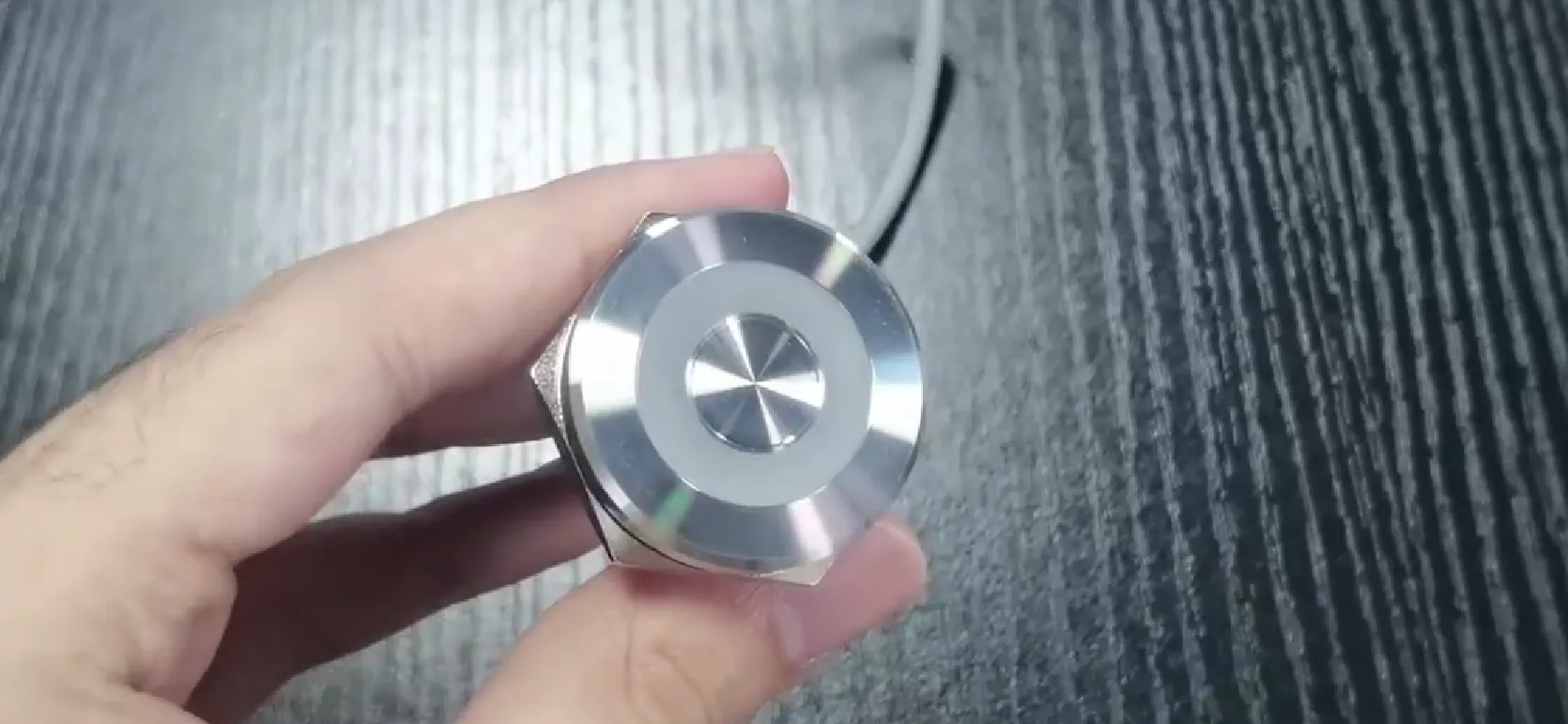
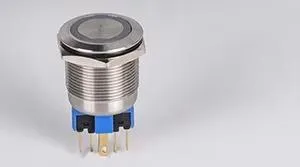
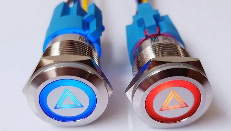
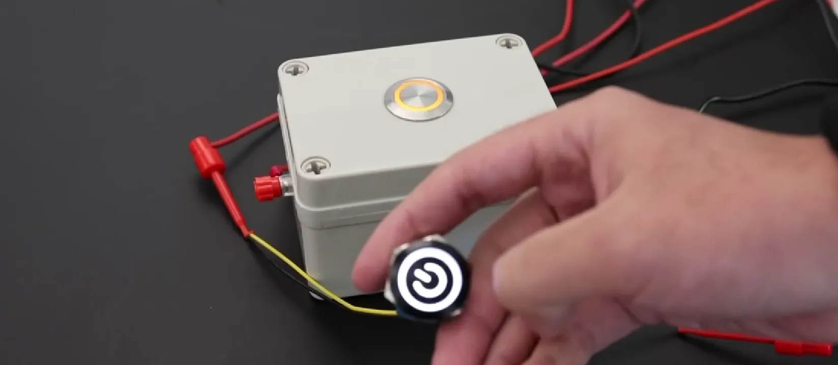
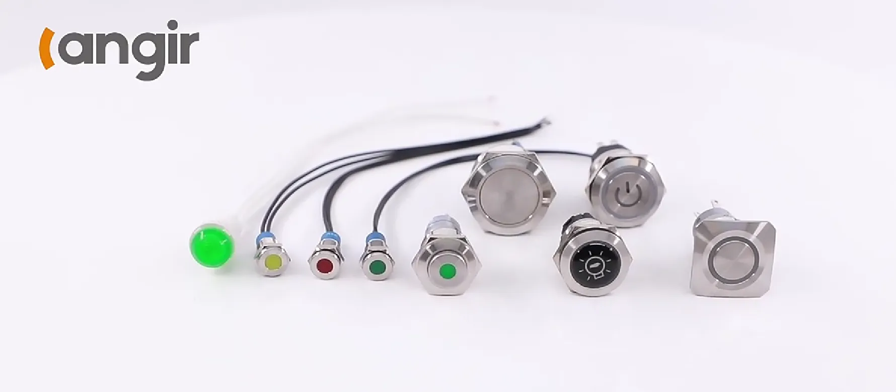
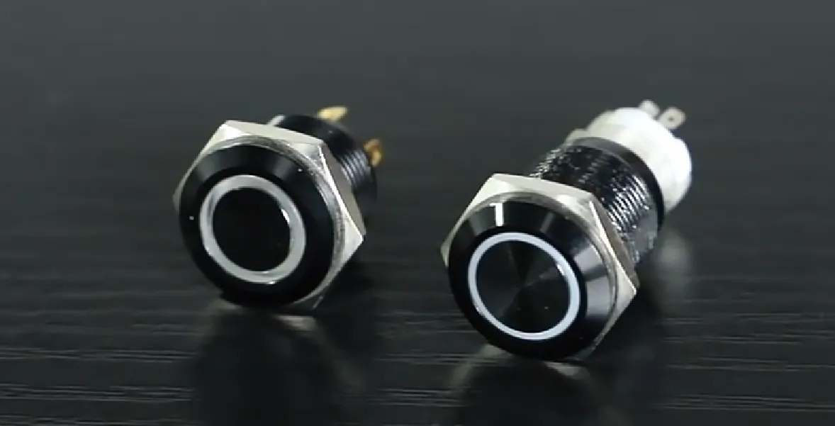
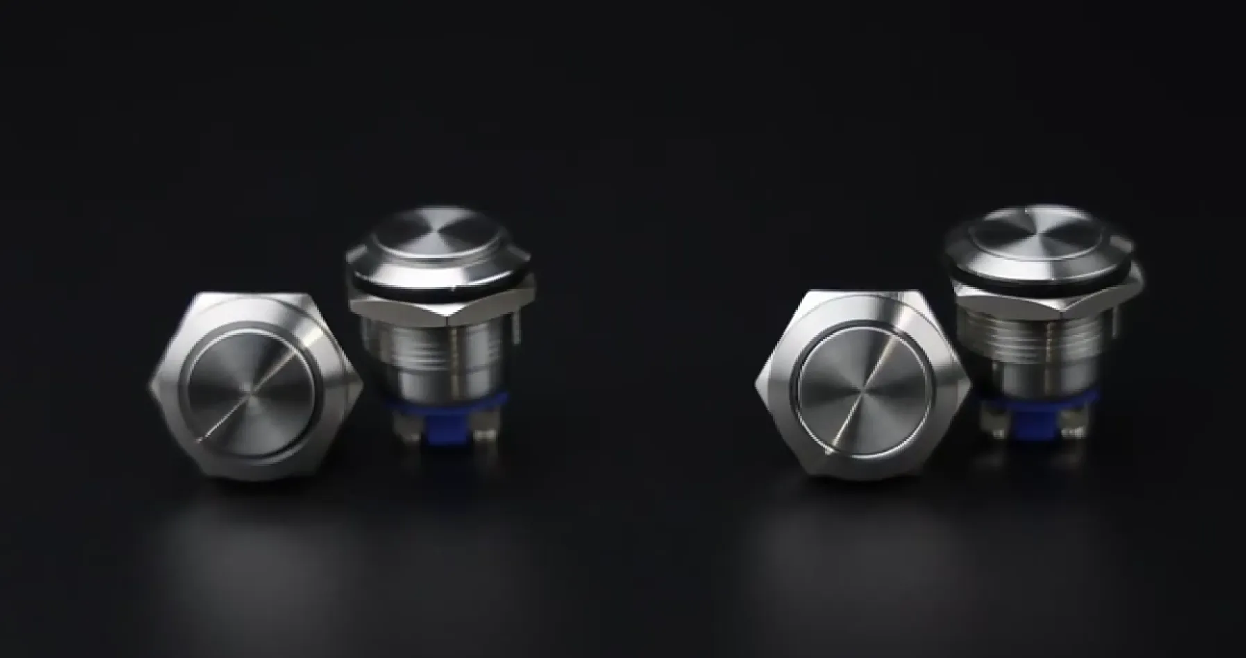
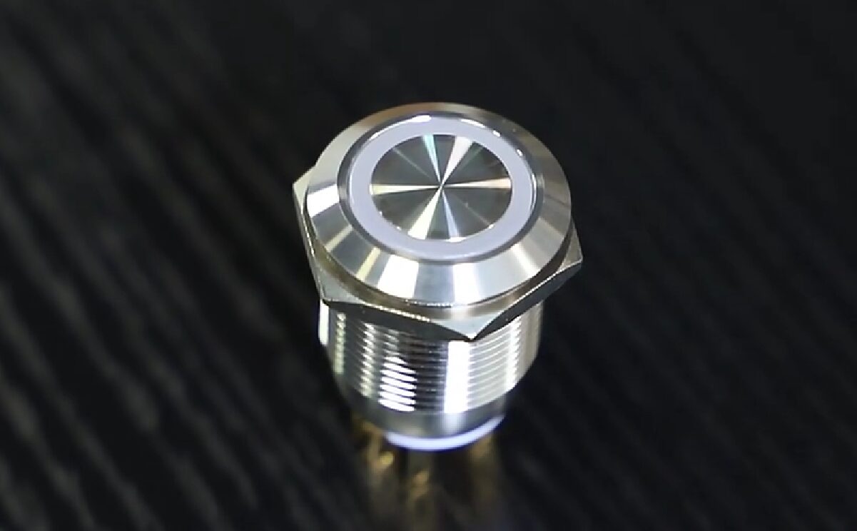
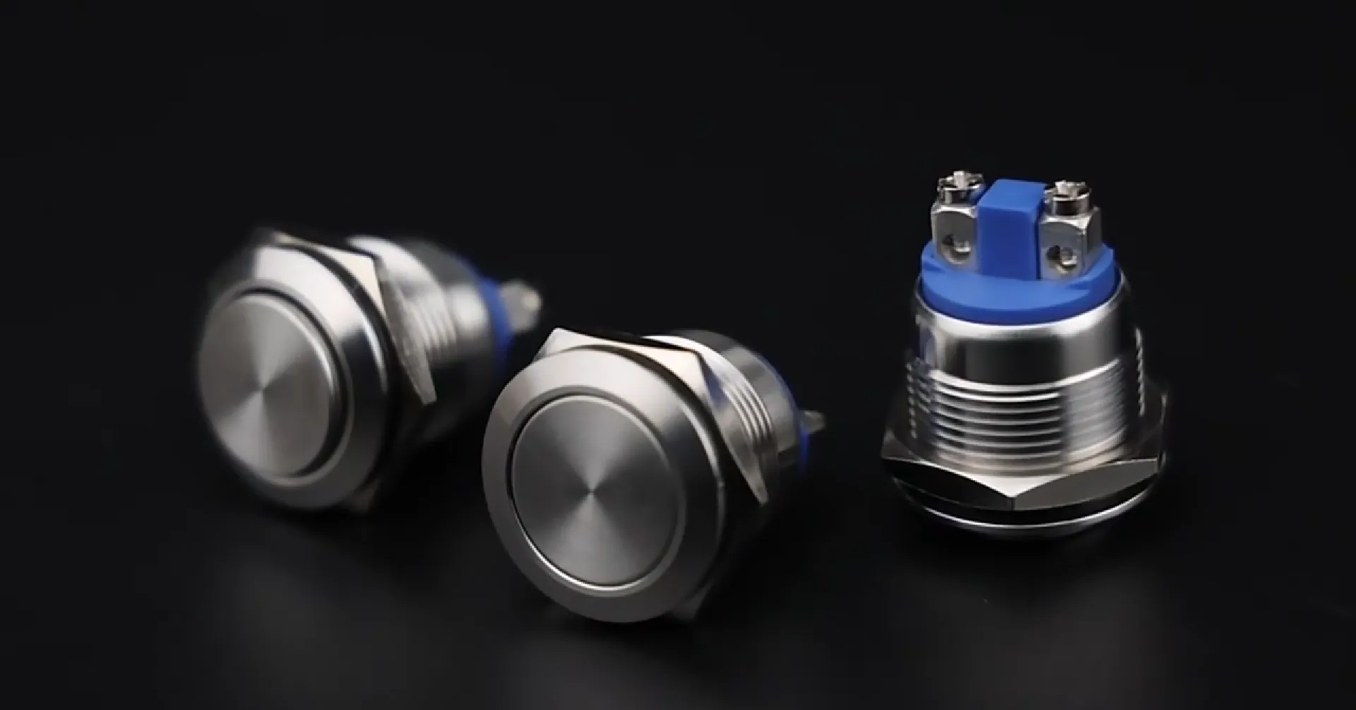
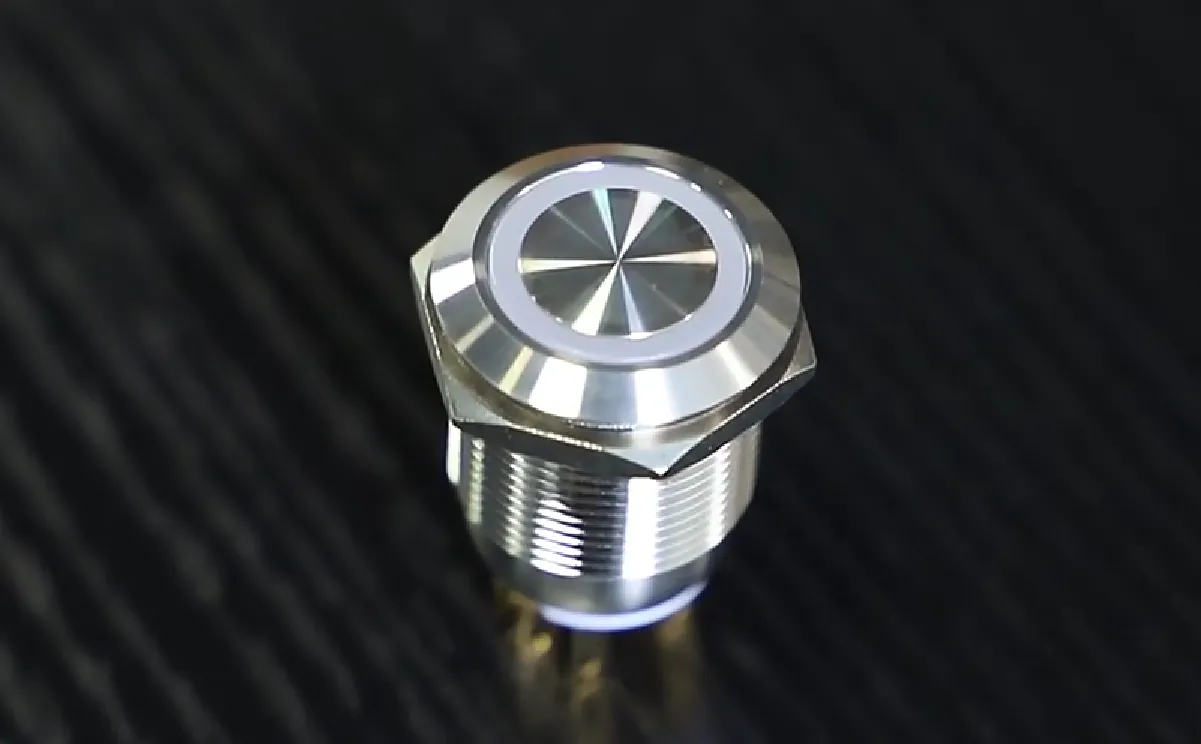
    A piezo electric switch is a cutting-edge, solid-state push button engineered to convert mechanical stress directly into a precise electrical signal through the inherent piezoelectric effect. This innovative design means no chemical cells, no cumbersome charging cycles, and absolutely no downtime for battery replacements—simply a finger press generating the exact voltage needed to flawlessly close a circuit. Langir’s piezo switches rely on a meticulously crafted crystal or ceramic element that momentarily deforms under pressure, instantly sending a clean pulse to the control electronics before effortlessly returning to its original shape, entirely free from wear.


    How Piezo Electric Switches Operate Without Batteries

    Contact Langir for Custom Piezo Switches


    The Foundational Principle: Unpacking the Piezoelectric Effect

    The piezoelectric effect precisely describes how specific materials—such as high-grade quartz or lead zirconate titanate (PZT)—generate an electric charge when subjected to mechanical compression or bending. Within a Langir piezo switch, this crystal lattice undergoes a minute, controlled shift under applied force, effectively separating charge centers and creating an instantaneous voltage difference. This precisely generated charge forms the brief, reliable pulse that seamlessly triggers a relay or microcontroller input.

    With this foundational understanding of crystal-to-charge conversion, let’s explore how this simple pressure translates into a reliable, usable signal.


    Key Materials and the Piezoelectric Principle

    The piezoelectric effect, the fundamental principle underpinning Langir’s piezo switches, is the inherent ability of certain advanced materials to generate an electric charge in direct response to applied mechanical stress. Materials like high-purity quartz and lead zirconate titanate (PZT) exhibit this crucial property, which is indispensable for the switch’s flawless operation.


    IEEE, “Piezoelectric Materials for Sensors and Actuators” (2022)

    This authoritative research provides the scientific bedrock for understanding how mechanical pressure is flawlessly converted into electrical energy within Langir’s piezo switches, precisely as described in this article.


    From Force to Function: The Energy Generation Process in Piezo Switches

    When you actuate a Langir piezo switch, the applied force precisely deforms its ceramic element by mere microns. This minuscule, controlled deformation expertly disturbs the internal electric dipoles, initiating an electron flow that yields an instantaneous voltage spike. Sophisticated electronics integrated within the switch meticulously capture that spike, condition it through a robust resistor-capacitor network, and transmit a clean, digital pulse to the downstream circuitry—all achieved without any external power supply.

    This direct and efficient energy conversion is precisely why Langir’s piezo switches operate with unwavering reliability, entirely free from external power sources or batteries.


    The Core Advantage: Why Piezo Switches Are Inherently Battery-Free

    Langir’s piezo switches ingeniously harvest just enough energy from each press to flawlessly register the actuation. There is absolutely no requirement to store energy between presses, thereby eliminating the need for bulky capacitors or cumbersome rechargeable cells. Because the piezoelectric crystal itself serves as the direct power source, the switch remains perpetually ready whenever mechanical force is applied, decisively eliminating battery degradation and profoundly simplifying overall system design.


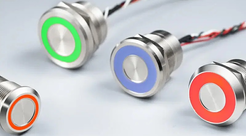
    The Advantages of Langir’s Battery-Free Piezo Electric Switches


    The Advantages of Langir's Battery-Free Piezo Electric Switches

    Contact Langir for Custom Piezo Switches

    Deploying Langir’s piezo switches without batteries delivers a distinct suite of benefits that are paramount in demanding industrial settings:


    1. Exceptional Durability and Extended Lifespan – With no moving contacts susceptible to wear, Langir’s piezo switches are engineered to endure over 50 million flawless actuations.
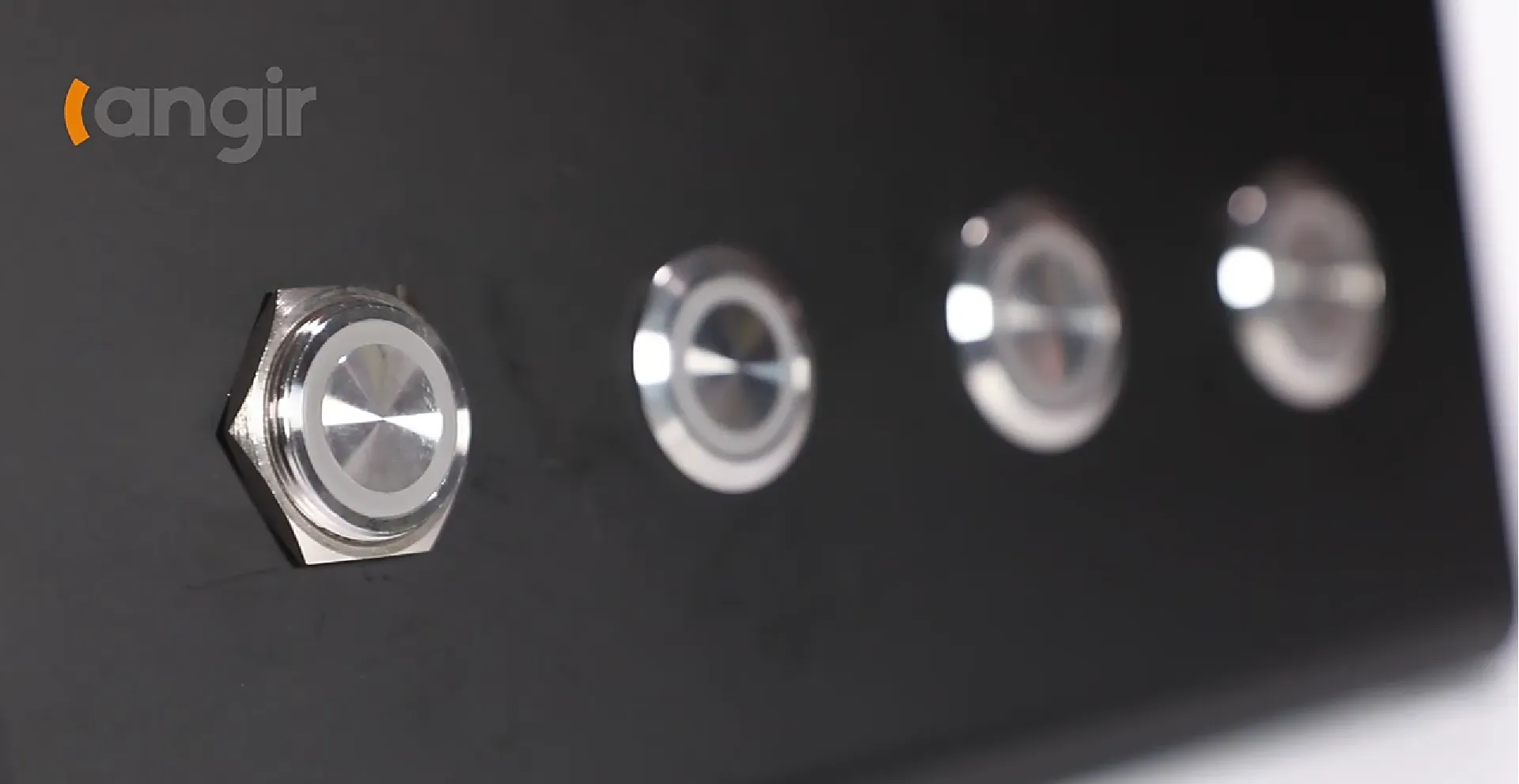
    2. Superior Environmental Resistance – Fully sealed to the highest IP68/IP69K standards, they effortlessly withstand moisture, dust, and aggressive wash-down chemicals.
    3. Minimal Maintenance and Significant Cost Savings – Experience zero battery replacements, eliminate lubrication schedules, and achieve minimal operational downtime.
    4. Optimized Energy Efficiency – Their self-generating pulses inherently reduce overall system power draw, actively supporting greener and more sustainable operations.


    Key Advantages of Langir’s Battery-Free Switches

    Langir’s piezoelectric switches offer profound advantages in industrial settings, including unparalleled durability, robust environmental resistance, and remarkably low maintenance requirements. Their meticulously sealed design and complete absence of moving parts contribute to an exceptionally long operational lifespan and unwavering reliable performance even in the harshest conditions, significantly reducing the need for frequent replacements or costly repairs.


    Smith, A., “Industrial Switch Technologies” (2023)

    This authoritative research further validates the superior performance and inherent advantages of piezo switches, particularly in the rigorous demands of industrial applications, setting them apart from conventional alternatives.

    These compelling advantages naturally lead us to a direct comparison with traditional battery-powered and mechanical switch alternatives.


    Langir’s Edge: Piezo Electric Switches Vs Battery-Powered and Mechanical Alternatives


    Langir's Edge Piezo Electric Switches Vs Battery-Powered and Mechanical Alternatives

    Contact Langir for Custom Piezo Switches

    For critical industrial control applications, the true cost of ownership is profoundly influenced by power demands and ongoing maintenance. The following table meticulously contrasts the key attributes of various switch types:


    Switch Category Power Mechanism Maintenance Profile Actuation Response
    Langir Piezo Electric Switch Self-generated via precise mechanical deformation Negligible—zero batteries, zero wear parts Instantaneous, unwavering digital pulse
    Battery-Powered Electronic Integrated battery or rechargeable cell Mandatory monitoring and routine replacement cycles Performance fluctuates with battery discharge
    Conventional Mechanical Momentary External power supply or direct mains voltage Frequent contact cleaning, lubrication, and eventual replacement Slower, prone to contact bounce, degrades with use

    Langir’s piezo designs decisively eliminate battery-related waste and the inherent contact fatigue of mechanical switches, consistently delivering unwavering pulses and requiring minimal upkeep for the most demanding industrial control panels.


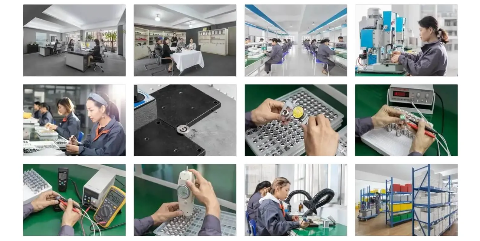
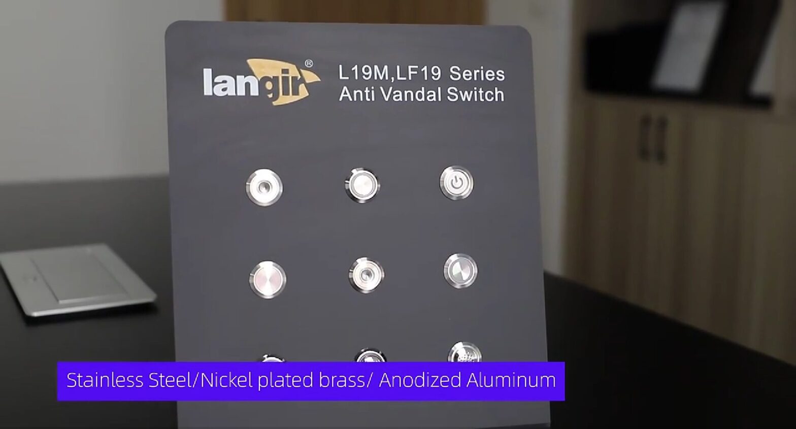
    Langir’s Commitment: Precision Manufacturing and Customization of Battery-Free Piezo Switches

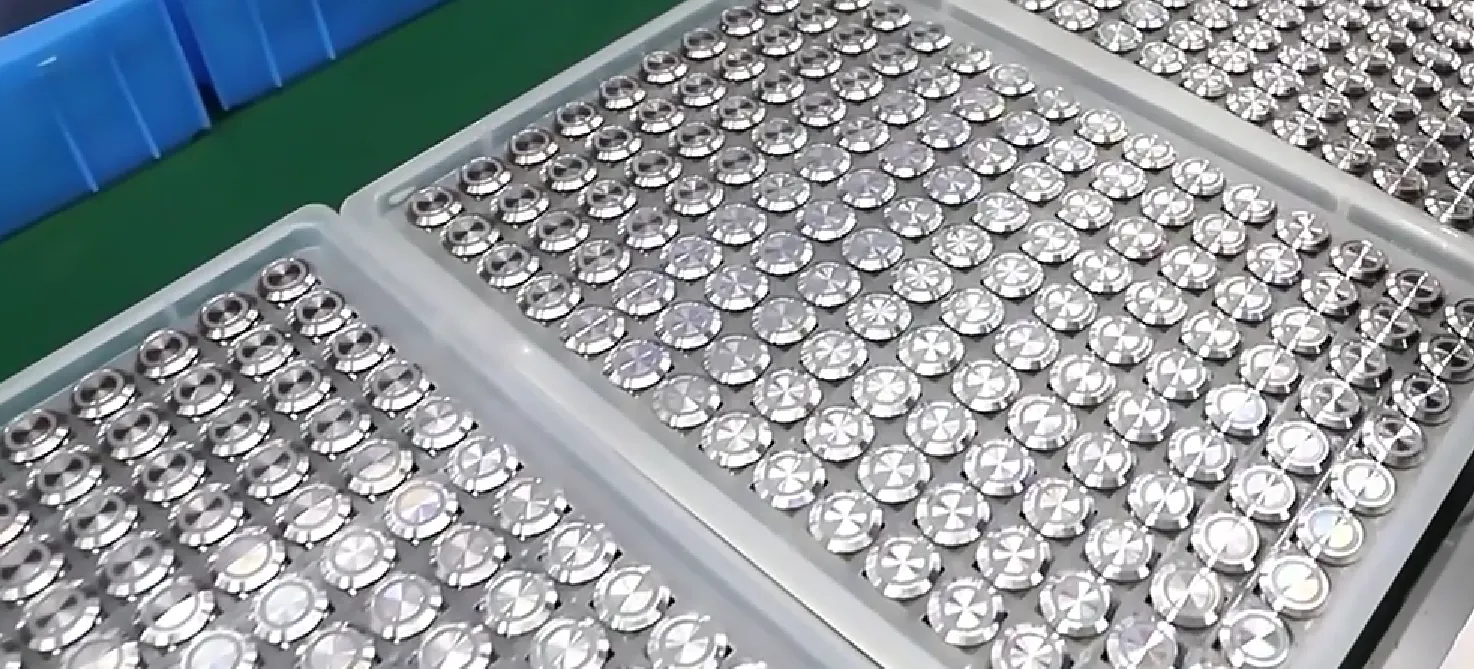
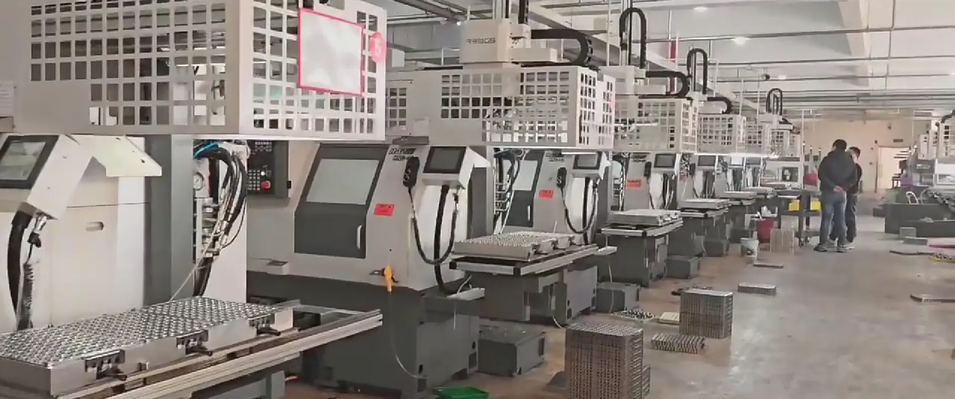
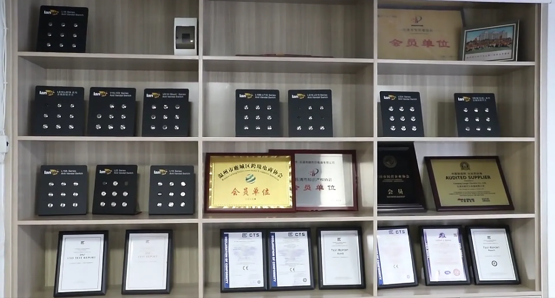
    Langir Electric has proudly specialized in advanced piezo push button switches since 2009, consistently earning ISO 9001 certification and serving over 10,000 discerning clients worldwide. Our state-of-the-art Wenzhou facility seamlessly integrates precision crystal bonding, high-pressure sealing, and rigorous multi-stage testing to ensure every battery-free switch meticulously meets and exceeds IP68/IP69K standards.


    Langir's Commitment: Precision Manufacturing and Customization of Battery-Free Piezo Switches

    Contact Langir for Custom Piezo Switches


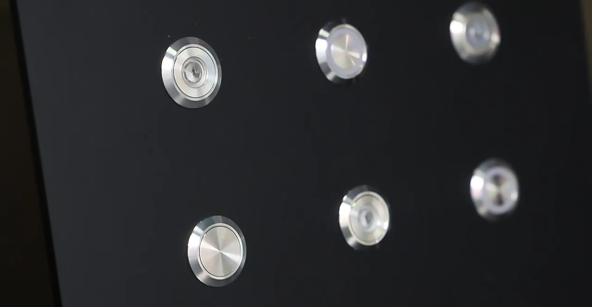
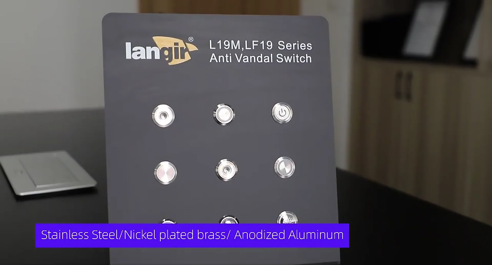
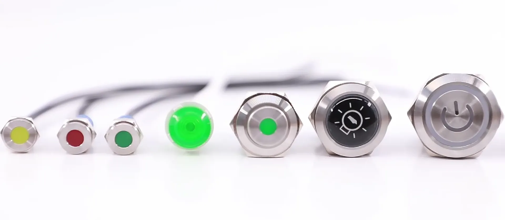
    Tailored Excellence: Customization Options for Langir’s Piezo Switches

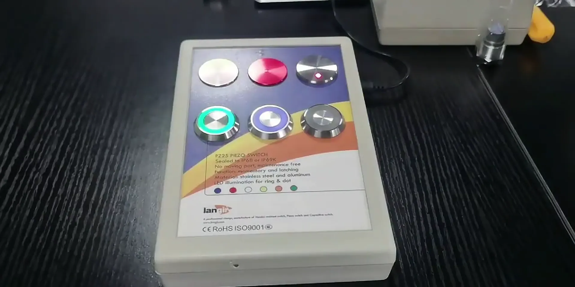
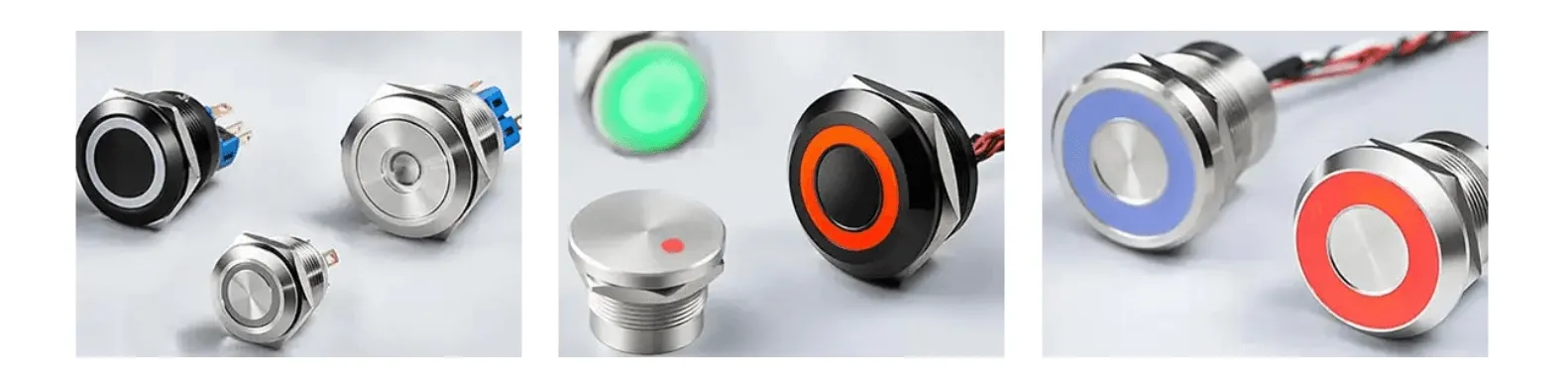
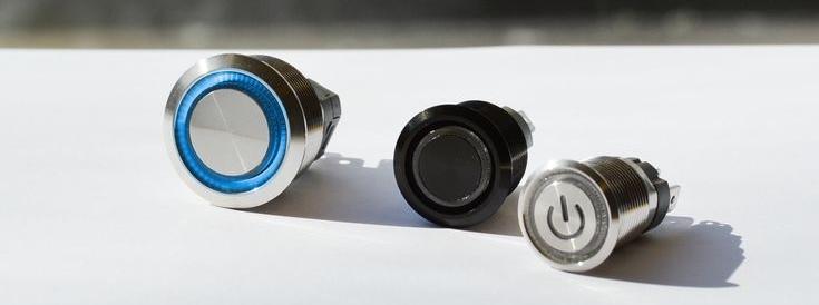
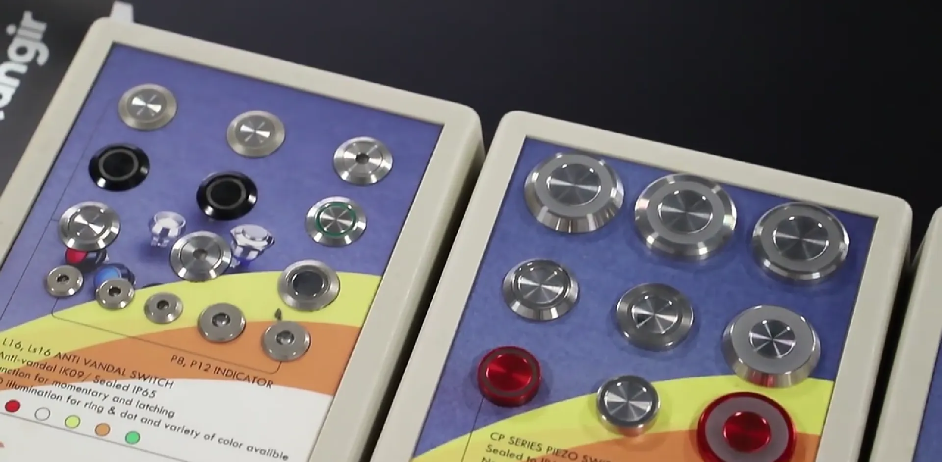
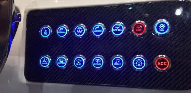
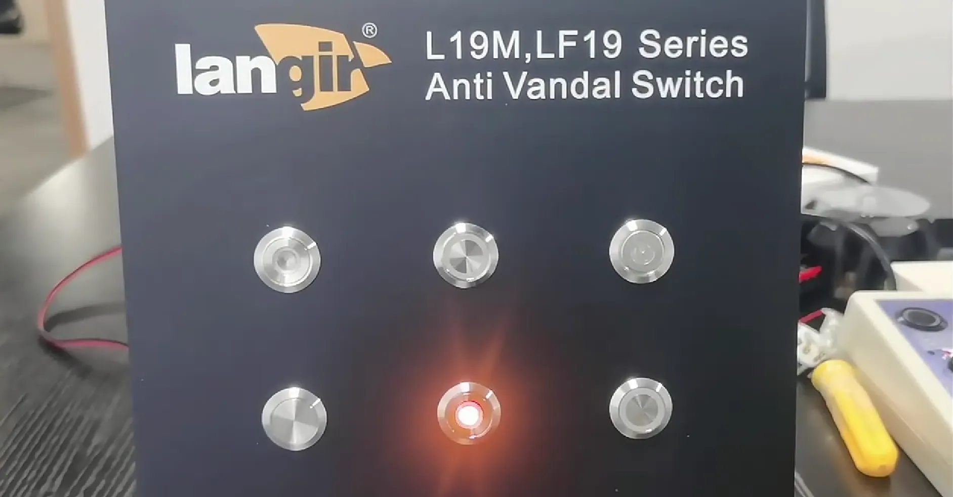
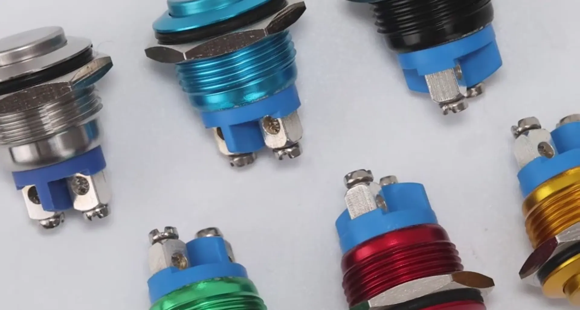
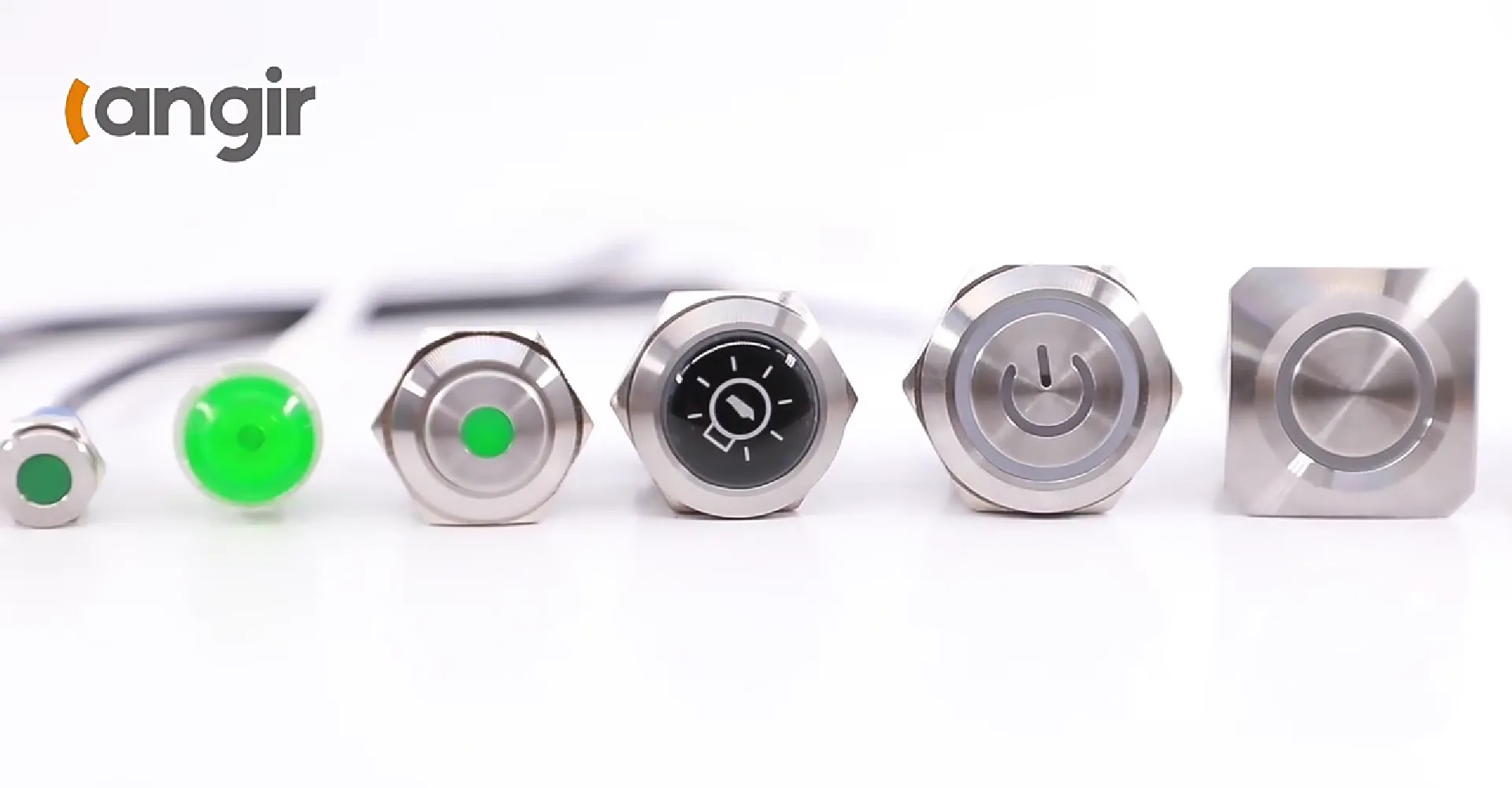
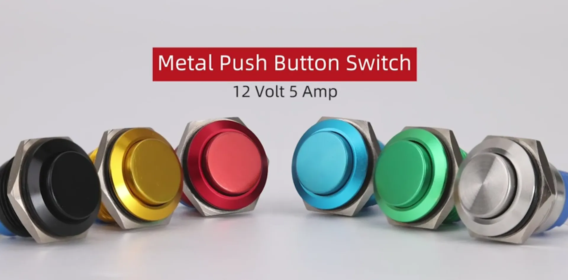
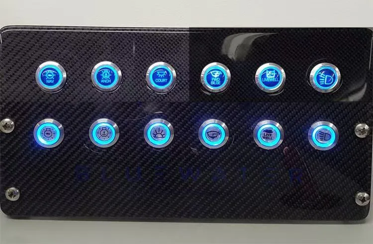
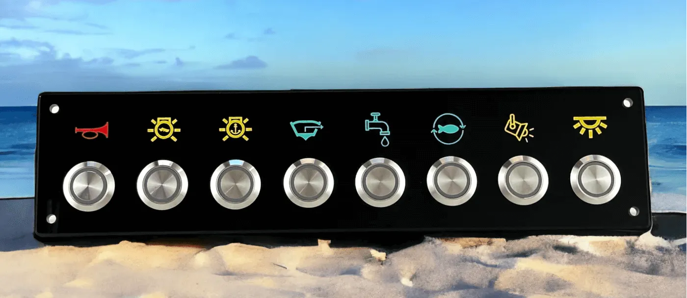
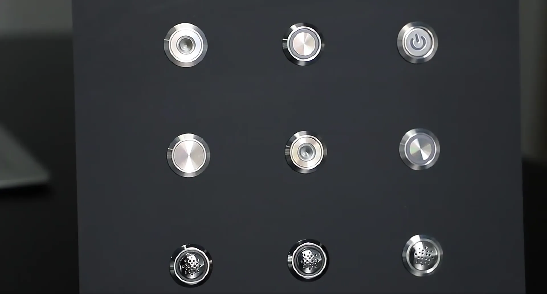
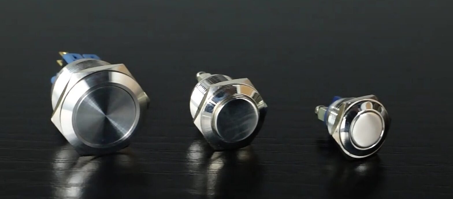
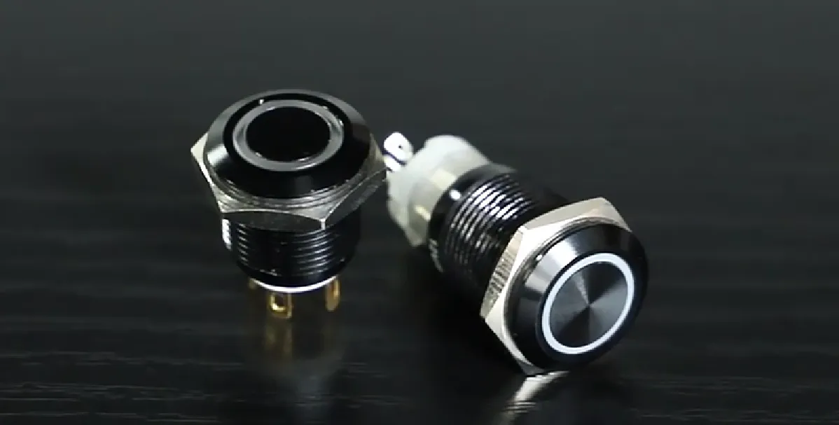
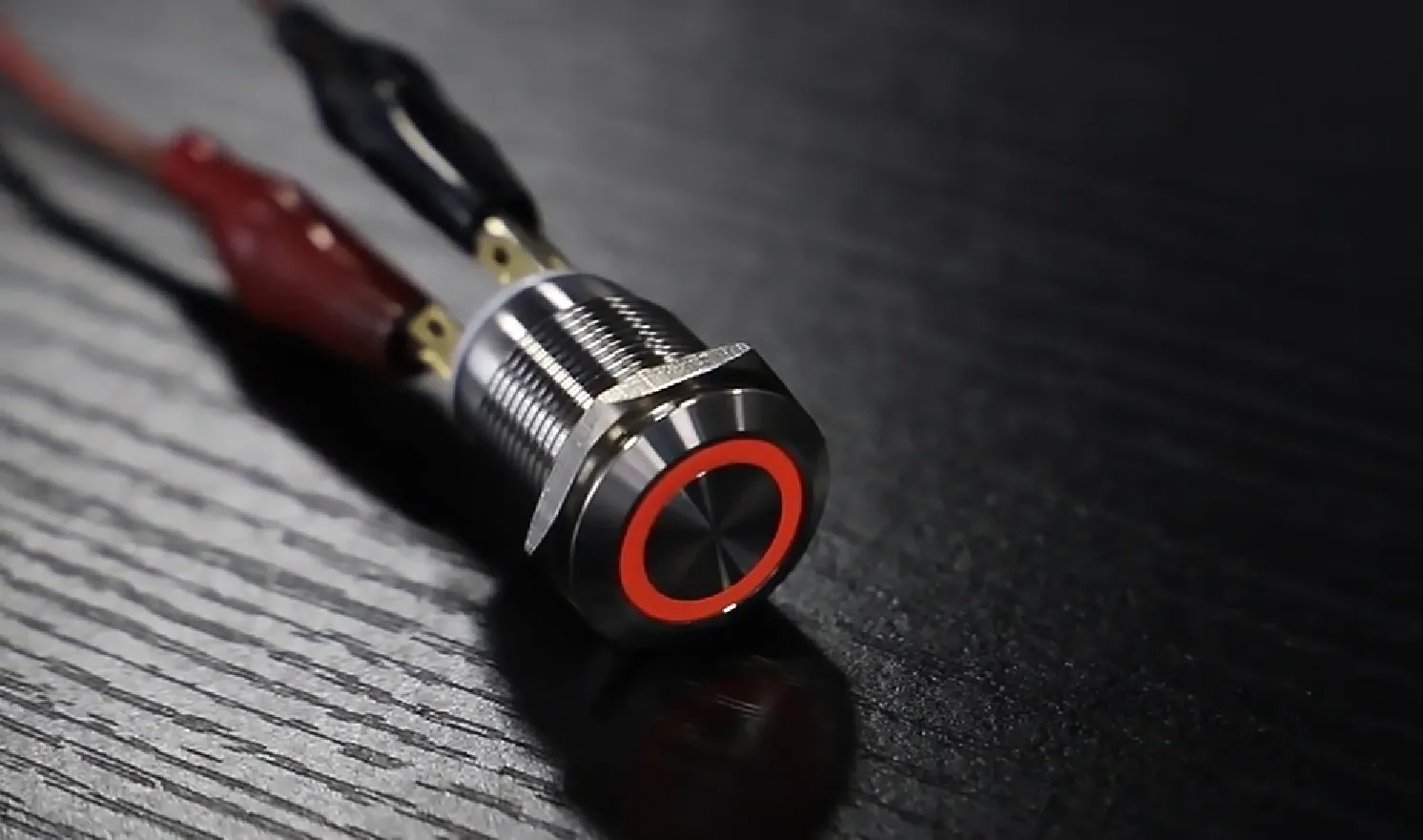
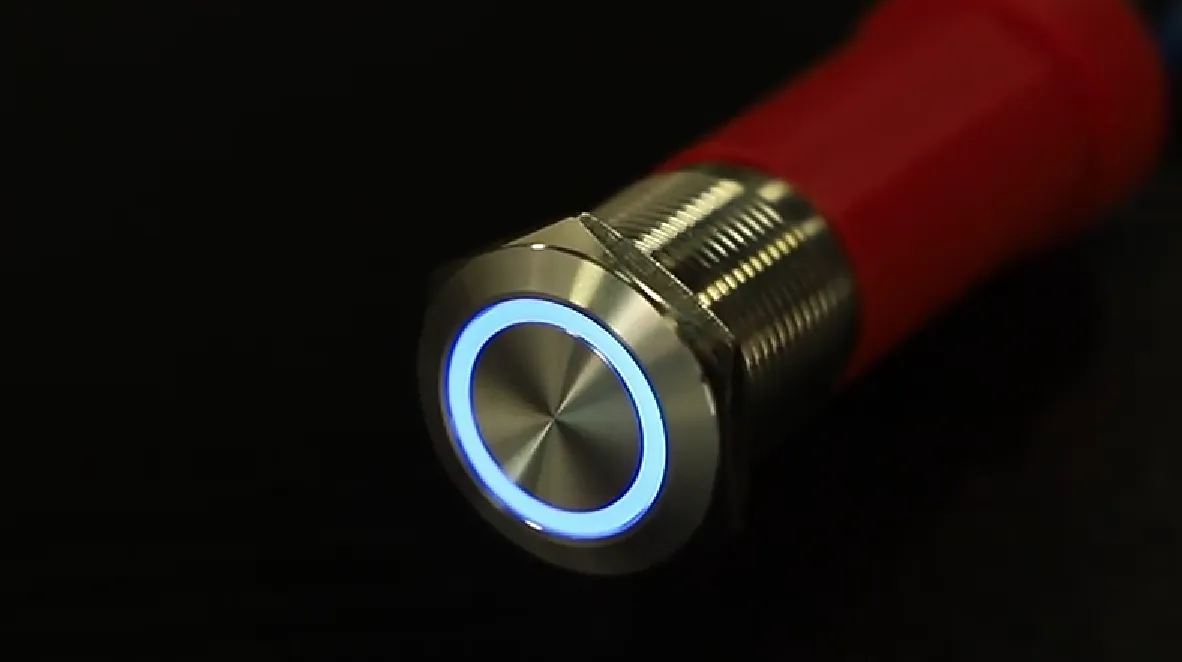
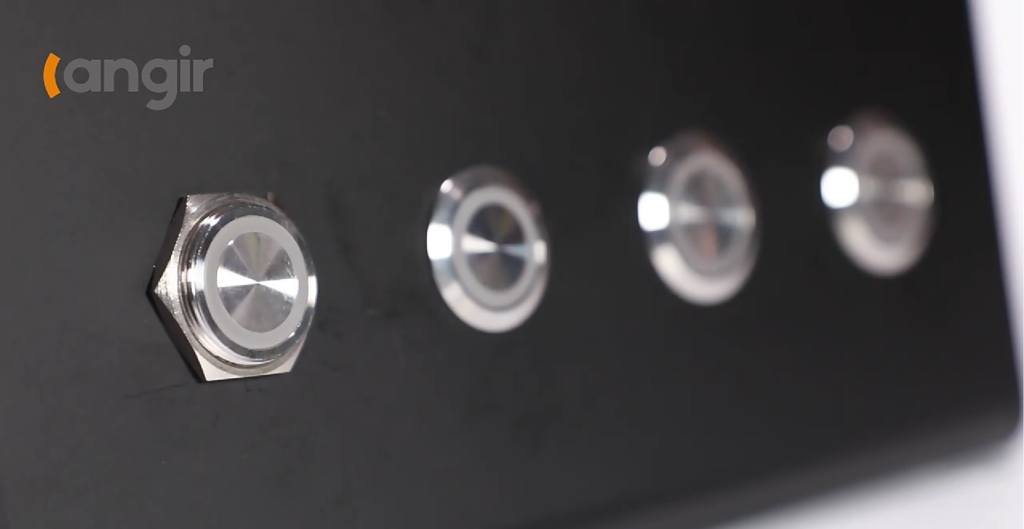
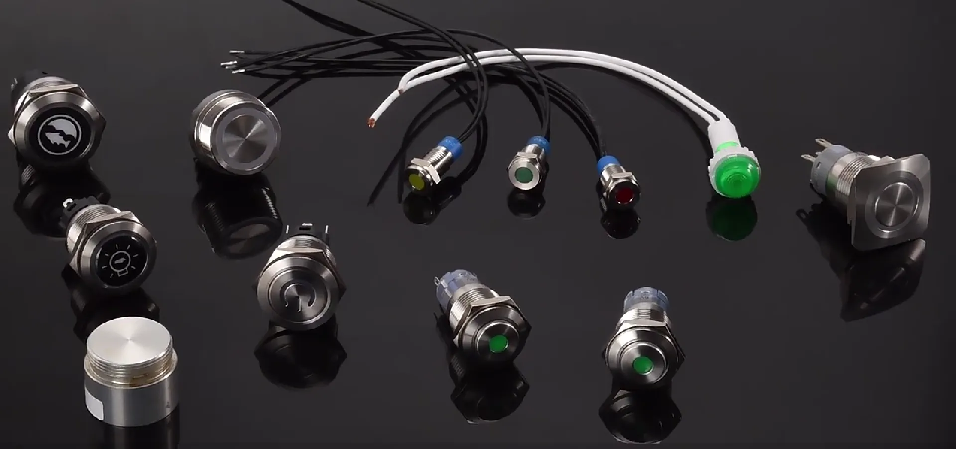
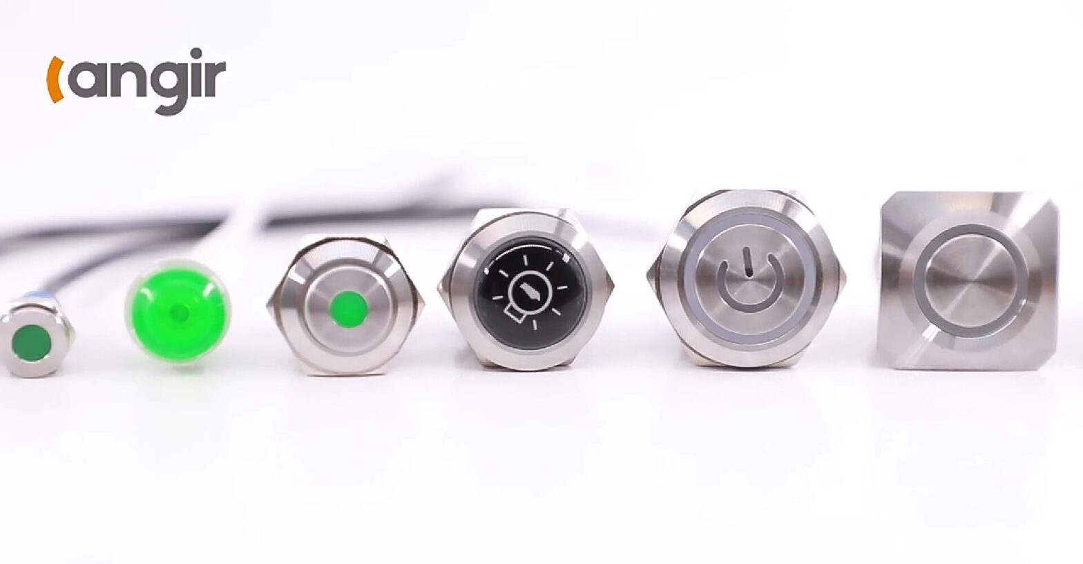
    Clients are empowered to select from premium stainless steel, durable brass, or robust plastic housings, specify custom cap colors and finishes, integrate vibrant LED illumination in any desired color, and choose from diverse mounting styles ranging from anti-vandal panels to compact PCB modules. We also offer intricate engravings, sophisticated backlighting patterns, and specialized encoded switch types for truly bespoke control interfaces.

    These extensive options empower engineers to perfectly align aesthetics, tactile feedback, and critical functionality, ensuring a seamless transition from concept to high-volume production.


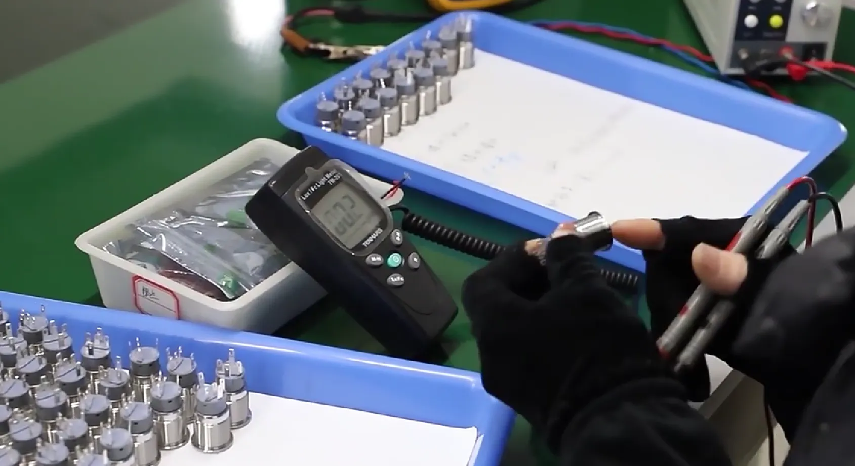
    Unwavering Reliability: Langir’s Rigorous Durability and Environmental Resistance Testing

    Every single Langir switch undergoes exhaustive thermal cycling, prolonged salt-spray exposure, and over 1,000,000-actuation endurance tests. Seals and adhesives are meticulously selected for their superior chemical-resistance, ensuring flawless performance in challenging food processing or corrosive coastal environments. Our stringent quality control protocols include automated electrical testing to verify absolute pulse integrity even under the most extreme conditions.

    This meticulous manufacturing process directly translates into field-proven, unwavering reliability for the most demanding industrial operations.


    The Ultimate Choice: Why Langir’s Battery-Free Piezo Switches Dominate Industrial Applications

    In critical sectors such as automation, transportation, and public safety, the costs associated with downtime escalate rapidly. Langir’s self-powered switches decisively eliminate battery-related failures and contact wear, guaranteeing consistent, peak performance in moisture-prone or high-vibration environments. This inherent reliability directly drives smoother production workflows and substantially lowers lifetime service expenses.


    Piezo Switch Power and Battery Independence | FAQs


    Piezo Switch Power and Battery Independence FAQs

    Contact Langir for Custom Piezo Switches


    Do Langir’s Piezo Electric Switches Require Batteries for Operation?

    Absolutely not. Langir’s piezo switches ingeniously generate the actuation pulse by precisely deforming a piezoelectric element under mechanical pressure, ensuring they never rely on batteries for their standard operation.

    Each press flawlessly converts kinetic energy directly into a precise voltage spike that the switch’s integrated electronics meticulously capture and transmit to your controller.


    The Mechanism Unveiled: How Electrical Energy is Generated Without a Battery in Piezo Switches

    A high-performance piezoelectric crystal or ceramic element flexes with precision under fingertip force, causing an internal charge displacement and a brief, potent voltage output. That instantaneous energy expertly triggers a clean digital signal, meticulously conditioned through the switch’s internal circuitry.

    This ingenious, direct conversion from mechanical force to electrical energy entirely bypasses the need for any chemical energy storage.


    Energy Storage Capabilities: Are Piezo Switches Designed for Continuous Power?

    Langir’s piezo switches are meticulously engineered for momentary pulses and do not incorporate onboard energy storage. Their brief voltage output occurs exclusively during each actuation, making them the ideal solution for precise signaling rather than continuously powering devices.

    Since each actuation instantly generates the precise energy required, there is no necessity for bulky capacitors or cumbersome rechargeable cells.


    Specific Scenarios: When Might a Battery Be Associated with Piezo Switches?

    Some highly specialized applications—such as powering integrated backlighting or sophisticated wireless transmitters—may incorporate separate, dedicated power sources. However, the core switching function itself remains fundamentally battery-free, and any illumination or wireless modules utilize their own independent energy supplies, entirely separate from the piezo element.


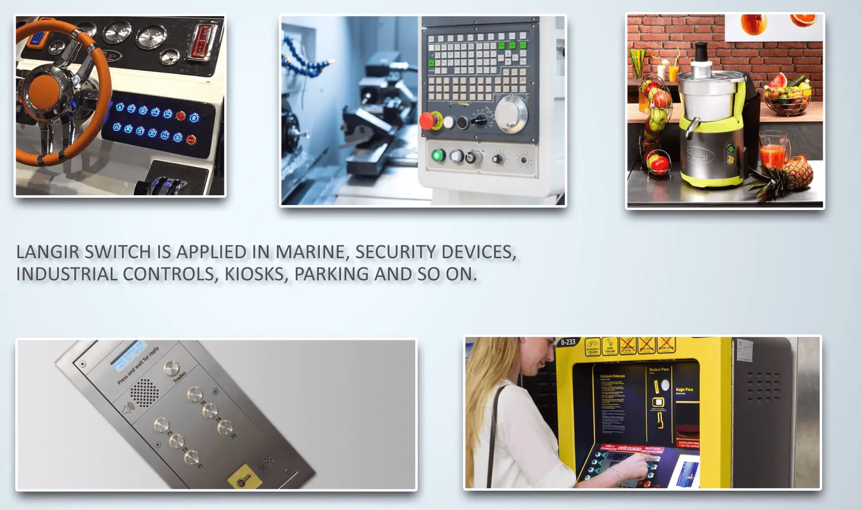
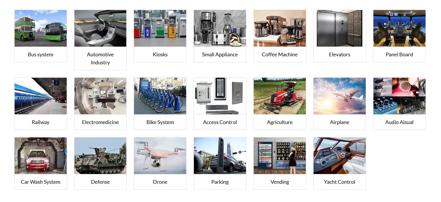
    Industrial Applications Thriving with Langir’s Battery-Free Piezo Electric Switches

    Langir’s piezo switches are engineered to excel in environments where unwavering durability and pristine operation are paramount.


    Industrial Applications Thriving with Langir's Battery-Free Piezo Electric Switches

    Contact Langir for Custom Piezo Switches


    Enhancing Reliability: Langir’s Battery-Free Piezo Switches in Harsh Industrial Settings

    Their meticulously sealed design and complete absence of contact wear deliver consistently superior performance in demanding wash-down food processing plants, rugged offshore rigs, and dust-filled foundries. The elimination of battery leaks or corroded contacts translates directly into fewer emergency repairs and significantly safer operation under the most extreme conditions.

    This robust solid-state actuation significantly minimizes unexpected failures, thereby ensuring uninterrupted and efficient production.


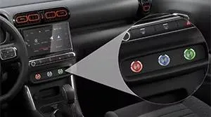
    Industry Preference: Why Piezo Switches Are Chosen for Medical, Automotive, and Consumer Electronics

    In critical medical devices, hygiene and sterilization are paramount—Langir’s sealed piezo buttons effortlessly withstand aggressive chemicals and rigorous cleaning protocols. Automotive controls demand vibration-resistant, exceptionally long-life switches that perform flawlessly. Compact consumer gadgets leverage our thin, battery-free switches for sleek, maintenance-free interfaces.

    Across these diverse industries, our self-powered designs streamline critical certification processes and substantially reduce costly service interventions.


    Optimizing Efficiency: Battery-Free Operation in Automation and Control Panels

    By decisively eliminating auxiliary power rails or cumbersome battery compartments, control panels become inherently simpler to wire, commission, and maintain. Langir’s self-generating switches significantly reduce wiring complexity and seamlessly support lower-power PLC or microcontroller designs, effectively cutting cabinet size and installation costs.

    This inherent efficiency directly translates into the development of leaner, more agile manufacturing lines.


    Ordering Bulk and Customized Battery-Free Piezo Switches from Langir


    Ordering Bulk and Customized Battery-Free Piezo Switches from Langir

    Contact Langir for Custom Piezo Switche


    Seamless Process: Steps to Request Custom Bulk Piezo Switch Manufacturing


    1. Precisely define your panel or PCB mount requirements and critical environmental specifications.
    2. Select your preferred housing material, illumination options, and engraving details.
    3. Submit your detailed 2D/3D drawing, or allow our expert engineers to finalize the design for you.
    4. Approve prototypes for perfect form, fit, and function.
    5. Confirm your bulk quantities and desired lead time for production.

    This meticulously streamlined process ensures your projects remain precisely on schedule and well within budget.


    Dedicated Partnership: Langir’s Support for Tailored Industrial Solutions

    Our dedicated project managers will expertly guide you from initial concept through comprehensive design validation, providing essential technical datasheets, precise sample builds, and thorough in-house testing reports. Our highly skilled engineering teams are readily available for on-site or virtual assistance, ensuring seamless integration into your existing control architecture.

    Our responsive service and ISO-certified workflows are meticulously designed to safeguard your critical timelines and precise specifications.


    Connect with Langir: Access Our Product Catalog and Contact Information

    Explore our full, extensive range of advanced piezo push button switches and bespoke custom solutions, or reach out directly for prompt quotes and expert technical support. Our global sales team stands ready to design, sample, and deliver superior battery-free switches in bulk quantities.

    Langir’s piezo electric switches decisively eliminate battery constraints by ingeniously harnessing the piezoelectric effect to generate each actuation pulse precisely on demand. Their solid-state reliability, extreme sealing capabilities, and remarkably low-maintenance profile make them the perfect choice for harsh industrial, critical medical, and demanding transportation controls. Langir Electric combines ISO 9001 certified manufacturing, extensive customization capabilities, and rigorous multi-stage testing to deliver battery-free piezo switches that flawlessly endure millions of cycles in the most challenging environments. Ready to simplify your next control panel design and significantly reduce lifetime service costs? Reach out to our expert team today for unparalleled bulk or bespoke piezo switch solutions.


    [/vc_column_text][/vc_column][/vc_row][vc_row][vc_column][vc_zigzag]

    Get Custom Quote
    We’ll get back to you within 12 hours.
    Drag & Drop Files, Choose Files to Upload You can upload up to 3 files.
    [/vc_column][/vc_row][vc_row][vc_column][vc_zigzag][/vc_column][/vc_row]

  • Can Piezo Switches Work with Boiling Water: What Experts Say

    Can Piezo Switches Work with Boiling Water: What Experts Say

    [vc_row][vc_column][vc_column_text]


    Imagine your control panel enduring daily immersion in boiling water. Langir piezo switches, engineered with solid-state design and premium materials, deliver unwavering reliability in liquids approaching 100 °C—a critical advantage for industrial production lines demanding both extreme durability and stringent hygiene. This comprehensive guide will reveal the inherent resilience of piezo switch technology, delve into their temperature thresholds and robust IP68/IP69K ratings, showcase their real-world utility in food processing, medical devices, and outdoor equipment, provide essential maintenance and troubleshooting insights, and demonstrate how Langir crafts bespoke solutions for continuous boiling water exposure.


    Unveiling Piezo Switches: Engineered for Extreme Environments

    Piezo switches represent a pinnacle of solid-state push-button technology, transforming mechanical force into a precise electrical signal without any moving components. This fundamental design ensures unparalleled longevity and inherent resilience. Their hermetically sealed construction provides formidable resistance against dust, moisture, vibration, and temperature extremes, positioning them as the definitive choice for industrial control applications in the most demanding conditions.


    Unveiling Piezo Switches Engineered for Extreme Environments

    Contact Langir for Custom Piezo Switches


    The Unyielding Durability of Piezo Switches in Challenging Conditions

    The inherent robustness of piezo switches stems directly from their solid-state architecture and the meticulously selected materials employed in their fabrication. This innovative design eradicates the vulnerabilities of moving parts, significantly boosting their operational lifespan and resilience against pervasive environmental stressors such as dust, moisture, vibration, and temperature fluctuations, thereby making them indispensable for rigorous industrial deployments.


    Langir, “Can Piezo Switches Work with Boiling Water? Durability, Temperature Limits, and Industrial Applications” (2024)

    This foundational research unequivocally validates the assertions within this article regarding the exceptional durability and unwavering resilience of piezo switches when deployed in the most challenging operational environments.


    Solid-State Superiority: The Core of Piezo Switch Durability

    At the heart of every piezo switch lies a sophisticated piezoelectric ceramic element. This component precisely flexes under applied pressure to generate an electrical signal, completely bypassing the need for conventional contacts and hinges—the very points most susceptible to wear and failure.

    This innovative design yields several critical advantages:


    1. Zero Moving Parts – Eradicates mechanical failure points, ensuring an operational lifespan exceeding 50 million cycles.
    2. Consistent Solid-State Output – Delivers uniform actuation force and precise pulse timing, critical for reliable system integration.
    3. Exceptional Vibration Resistance – The robust ceramic element maintains unwavering stability even under severe shock and persistent vibration.

    Collectively, these inherent advantages guarantee uninterrupted operational integrity in the most demanding industrial settings, laying the groundwork for advanced material-level defense against extreme heat and corrosive agents.


    Material Science: Crafting Piezo Switches for Heat and Corrosion Resistance

    The table below details the primary materials employed in industrial-grade piezo switches, highlighting their specific protective characteristics against thermal and corrosive challenges.


    Material Heat Tolerance Corrosion Resistance
    Stainless Steel 316L Exceptional thermal stability, melting point up to 500 °C Superior resistance to acids, alkalis, and salt spray
    Piezoelectric Ceramic (PZT) Maintains stability up to 300 °C Inherently electrically inert and impervious to moisture
    Aluminum Alloy Reliable for continuous operation up to 200 °C Offers robust corrosion resistance when anodized


    Optimizing Performance: Material Properties and Thermal Resilience

    This article underscores the paramount importance of meticulous material selection in defining the operational temperature envelopes of piezo switches. We delve into the specific heat tolerance and corrosion resistance attributes of Stainless Steel 316L, piezoelectric ceramic (PZT), and aluminum alloy. These intrinsic material properties are absolutely critical for ensuring the unwavering performance of our switches when subjected to severe thermal stress and aggressive chemical environments.


    Langir, “Can Piezo Switches Work with Boiling Water? Durability, Temperature Limits, and Industrial Applications” (2024)

    This authoritative citation reinforces the article’s detailed examination of the materials integral to piezo switch construction and their profound influence on performance within high-temperature operational settings.

    Each meticulously engineered material layer functions as an impenetrable barrier, providing robust defense against thermal stress and chemical degradation, thereby empowering piezo switches to sustain peak performance even under the most extreme temperature conditions.


    Defining Operational Limits: Piezo Switch Temperature Ranges

    Standard Langir piezo switch models are engineered to operate reliably within the following temperature specifications:


    • −40 °C to 75 °C – The established industrial standard for general-purpose metal switches.
    • −40 °C to 125 °C – Achieved by high-temperature variants incorporating reinforced ceramics.
    • −40 °C to 150 °C – Attainable through custom-engineered solutions featuring specialized adhesives and advanced sealing technologies.

    These meticulously defined ranges represent an optimal balance between ceramic stability, seal integrity, and electronic reliability, ensuring peak performance across a multitude of demanding process applications.


    The Boiling Point Challenge: Standard Piezo Switches at 100 °C

    No, standard piezo switches, typically rated for up to 75 °C, are not designed for continuous immersion in 100 °C boiling water. Such exposure carries a significant risk of seal degradation or ceramic depolarization. While IP69K-rated models are engineered to endure brief, high-pressure washdowns, prolonged and continuous exposure to boiling water necessitates specialized, custom-engineered design modifications.


    The Boiling Point Challenge Standard Piezo Switches at 100 °C

    Contact Langir for Custom Piezo Switches


    Navigating the Extremes: Challenges of Piezo Switches in Boiling Water

    Piezo switches encounter three primary challenges when immersed in boiling water:


    • Thermal Shock – Abrupt and extreme temperature fluctuations can induce cracking in ceramic elements or cause housing deformation.
    • Seal Degradation – Elevated temperatures significantly accelerate the aging process of gaskets and the breakdown of bonding adhesives.
    • Continuous Immersion – Extended periods of water contact impose considerable stress on the internal electronic components.


    Understanding the 75 °C Threshold: Limitations of Standard Piezo Switches

    Manufacturers typically establish a 75 °C operational limit for standard models to mitigate the following critical risks:


    1. Epoxy Softening – Bonding adhesives experience a significant reduction in mechanical strength when temperatures exceed 80 °C.
    2. Ceramic Depolarization – Piezoelectric elements can irreversibly lose their sensitivity and functionality if exposed to temperatures above their critical Curie temperature.
    3. O-Ring Compression Set – Elastomer seals are prone to compression set, leading to leakage under prolonged thermal stress.

    Adhering to these design constraints is paramount for safeguarding the long-term reliability and performance of piezo switches in conventional industrial environments.


    Langir’s Expertise: Custom Piezo Switch Solutions for Boiling Water Environments

    Langir excels in engineering bespoke piezo switches specifically for boiling water applications. This is achieved through the meticulous selection of advanced high-temperature ceramics, the strategic replacement of standard epoxies with robust heat-resistant silicones, and the integration of sophisticated thermal isolation layers between the switch housing and its sensitive electronics. Furthermore, a food-grade PTFE gasket and a corrosion-proof 316L stainless steel front plate are incorporated to guarantee uninterrupted operation within 100 °C water baths. These precisely tailored designs not only preserve optimal electrical performance but also provide exceptional resistance to thermal shock, consistently meeting the most rigorous process demands.


    IP Ratings Explained: Ensuring Piezo Switch Performance in High-Temperature Liquids

    IP68 and IP69K certifications represent critical international standards for ingress protection against dust and water. They precisely quantify a switch’s capacity to withstand prolonged submersion and aggressive high-pressure, high-temperature washdowns—essential criteria for control devices operating in liquid-intensive environments.


    Contact Langir for Custom Piezo Switches

    Contact Langir for Custom Piezo Switches


    Decoding IP68: Comprehensive Water and Dust Protection

    An IP68 rating signifies that a switch is completely dust-tight and engineered to endure continuous submersion beyond 1 meter—commonly specified as 1.5 meters for a duration of 30 minutes. This superior level of sealing effectively shields all internal components from both particulate matter and moisture ingress, making it indispensable for submerged or perpetually wet operational environments.


    The Power of IP69K: Withstanding High-Pressure, High-Temperature Washdowns

    IP69K certification involves subjecting devices to intense 80 °C water jets, delivered at 80–100 bar pressure from various angles. Successful completion of IP69K testing unequivocally confirms that a switch’s seals and housing materials are robust enough to withstand the most aggressive cleaning protocols, a common requirement in demanding food processing and medical sterilization applications.


    IP69K and Boiling Water: Understanding the Limits

    While IP69K-rated piezo switches are engineered to withstand brief exposure to hot, pressurized water up to 80 °C, it is crucial to note they are not certified for continuous immersion in 100 °C boiling water. For applications demanding repeated sterilization cycles in boiling water, a bespoke design incorporating advanced ceramics and specialized high-temperature seals is absolutely essential to ensure sustained long-term performance.


    Applications in Extremes: Piezo Switches in High-Temperature Liquid Environments

    Piezo switches demonstrate unparalleled performance in any industrial setting where robust, hermetically sealed controls are imperative to withstand intense heat, pervasive moisture, and aggressive cleaning regimens.


    Applications in Extremes Piezo Switches in High-Temperature Liquid Environments

    Contact Langir for Custom Piezo Switches


    Enhancing Hygiene and Efficiency: Piezo Switches in Food & Beverage

    Food and beverage production lines demand hygienic switches capable of enduring frequent CIP (Clean-In-Place) cycles and hot water rinses. Piezo switches deliver:


    • Precise, vibration-free actuation, ideal for high-speed automated fill-seal machinery.
    • Hermetically sealed surfaces that actively inhibit bacterial growth, ensuring superior hygiene.
    • Full compatibility with high-pressure washdowns, facilitating rigorous sanitary maintenance protocols.

    These advanced features collectively streamline operational workflows while rigorously adhering to the most stringent safety and sanitation standards.


    Critical Control: Piezo Switches in Medical & Pharmaceutical Sterilization

    Within sterilization chambers and autoclaves, piezo switches offer distinct advantages:


    • Unwavering reliability even under repeated, intense steam sterilization cycles.
    • Ultra-smooth, crevice-free surfaces engineered to eliminate contamination risks.
    • Extended operational lifespan, significantly reducing costly equipment downtime.

    The inherent solid-state design of piezo switches perfectly aligns with the exceptionally stringent cleanliness and unwavering reliability demands of these critical industries.


    Built for the Elements: Piezo Switches in Outdoor & Industrial Machinery

    Outdoor control panels and industrial machinery are routinely exposed to harsh sunlight, heavy precipitation, and extreme temperature fluctuations. Piezo switches provide robust resistance through:


    • Robust UV-stabilized housings engineered to prevent plastic embrittlement and degradation.
    • Comprehensive salt-spray protection, essential for demanding marine and coastal environments.
    • Expansive operating temperature ranges, ensuring functionality from scorching desert heat to frigid arctic conditions.

    These formidable attributes collectively guarantee consistent, unwavering performance even in the planet’s most challenging and unpredictable environments.


    Maximizing Longevity: Maintenance & Troubleshooting for Piezo Switches in High-Temperature Liquids

    Proactive maintenance and prompt issue identification are paramount to significantly extending the operational lifespan of your piezo switches and preventing costly downtime in demanding thermal liquid applications.


    Maximizing Longevity Maintenance & Troubleshooting for Piezo Switches in High-Temperature Liquids

    Contact Langir for Custom Piezo Switches


    Optimizing Durability: Best Practices for Hot Liquid Environments

    To optimize the durability and performance of your piezo switches:


    1. Thoroughly rinse switches with clean, deionized water following each high-temperature cycle to eliminate any accumulated residue.
    2. Conduct monthly inspections of front plates and gaskets for any indications of corrosion or compression set.
    3. Implement a proactive schedule for preventive seal replacements, calibrated according to accumulated thermal exposure hours.

    Consistent, diligent care is essential for preserving the critical sealing integrity and ensuring unwavering actuation consistency of your switches over their extended operational lifetime.


    Troubleshooting Guide: Addressing Thermal Stress & Moisture-Related Issues

    Be vigilant for these common symptoms and apply the recommended remedies:


    • Increased Actuation Force – Clean or replace the gaskets to restore the switch’s smooth and responsive travel.
    • Intermittent Signals – Carefully dry internal contacts using a low-power heat gun, then meticulously reseal the housing.
    • Surface Pitting – Polish the stainless steel faceplate or consider upgrading to a superior, higher-grade alloy for enhanced resistance.

    Promptly addressing even minor issues is crucial to prevent any degradation in performance when switches are subjected to persistent heat and moisture.


    Tailored for Extremes: Langir’s Custom Piezo Switch Solutions

    Langir’s comprehensive customization services are meticulously designed to ensure that every piezo switch precisely meets your unique and demanding thermal and liquid exposure specifications.


    Tailored for Extremes Langir's Custom Piezo Switch Solutions

    Contact Langir for Custom Piezo Switches


    Precision Engineering: Material Selection for Boiling Water Performance

    The strategic selection of 316L stainless steel delivers unparalleled corrosion resistance at 100 °C, while advanced high-temperature ceramics meticulously preserve their sensitivity throughout rigorous steam cycles. Furthermore, the integration of high-performance PTFE gaskets is critical in preventing seal failure, thereby guaranteeing both uncompromising hygiene and unwavering reliability during continuous boiling water contact.


    Enhancing Resilience: Design Modifications for Thermal Shock Resistance

    The strategic incorporation of thermal breaks and specialized buffer layers between the switch housing and its sensitive electronics is paramount in minimizing the impact of rapid temperature shifts. Additionally, the use of flexible, high-temperature adhesives and advanced double-lip gaskets effectively absorbs thermal expansion and contraction, significantly reducing mechanical stress on both the piezo element and its critical seals.


    Your Custom Solution: Requesting a High-Temperature Liquid Piezo Switch

    To initiate a request for a custom-engineered piezo switch, precisely tailored for continuous boiling-water applications, we invite you to reach out for a comprehensive consultation and detailed quotation: Connect with Langir for Bespoke Solutions. Our expert engineering team will meticulously assess your specific thermal requirements and meticulously design a solution incorporating the optimal materials, advanced seals, and robust electronics.


    Comparative Analysis: Piezo Switches vs. Alternatives in Extreme Heat

    When subjected to extreme thermal conditions, piezo switches present distinct advantages and certain considerations when compared against conventional mechanical and capacitive switch alternatives.


    Comparative Analysis Piezo Switches vs. Alternatives in Extreme Heat

    Contact Langir for Custom Piezo Switches


    Unmatched Performance: Piezo Switch Advantages Over Mechanical & Capacitive Types


    Switch Type Durability Sealing Performance Lifespan
    Piezo Zero moving parts, ensuring unparalleled solid-state reliability Superior IP68/IP69K ratings, ideal for rigorous washdown protocols Exceeds 50 million cycles
    Mechanical Susceptible to contact wear and corrosion Typically limited to IP65–IP67 1–5 million cycles
    Capacitive Vulnerable to moisture interference Frequently limited to IP67 5–10 million cycles

    For high-temperature liquid applications, piezo switches consistently demonstrate superior performance in both sealing integrity and operational lifecycle.


    Considerations: Piezo Switch Limitations in Extreme Heat vs. Alternatives

    While piezo switches offer exceptional resilience, exceeding the 75 °C threshold necessitates meticulous material and seal selection. In contrast, certain capacitive designs may tolerate marginally higher ambient temperatures without requiring continuous immersion. It is important to note that customization, while providing tailored solutions, inherently introduces additional complexity and extends lead times, making standard capacitive modules a quicker deployment option when extreme extended temperature ranges are not the primary concern.

    Leading industrial teams consistently select piezo technology for its unparalleled washdown performance and extended cycle life, carefully weighing customization requirements against project timelines and budgetary considerations.

    Langir’s advanced solid-state switches, coupled with our robust sealing technologies and bespoke design services, are engineered to deliver exceptionally reliable control solutions for your most challenging high-temperature liquid applications.


    [/vc_column_text][/vc_column][/vc_row][vc_row][vc_column][vc_zigzag]

    Get Custom Quote
    We’ll get back to you within 12 hours.
    Drag & Drop Files, Choose Files to Upload You can upload up to 3 files.
    [/vc_column][/vc_row][vc_row][vc_column][vc_zigzag][/vc_column][/vc_row]

  • Does a Piezoelectric Switch Really Show Switching? Find Out!

    Does a Piezoelectric Switch Really Show Switching? Find Out!

    [vc_row][vc_column][vc_column_text]


    Piezoelectric switches convert mechanical force into precise, instantaneous electrical signals, offering unparalleled wear-free reliability in demanding industrial settings. While many manufacturers contend with switches prone to corrosion, jamming, or frequent replacement, piezoelectric push buttons deliver up to 50 million actuations, robust IP68 sealing, and ultra-low power consumption by eliminating traditional mechanical contacts. This comprehensive guide delves into the operational principles of piezoelectric switching, highlights its distinct advantages over mechanical and capacitive alternatives, outlines diverse real-world applications, and showcases how Langir Electric’s customizable solutions address both large-scale and specialized industrial requirements. Inside, you will explore:


    1. Defining the Piezoelectric Switch: The Science of Solid-State Operation
    2. Step-by-Step: Converting Mechanical Stress into Electrical Pulses
    3. Unmatched Durability, Environmental Resilience, and Hygienic Advantages
    4. Essential Applications: From Industrial Automation to Medical Interfaces and Wearables
    5. Langir Electric’s Solutions: Product Features, Customization, and Ordering Information
    6. Piezoelectric vs. Other Technologies: A Comparative Analysis and Market Outlook
    7. Optimizing Performance: Installation Best Practices and Maintenance for Longevity


    Understanding Piezoelectric Switches: Core Functionality Explained

    A piezoelectric switch operates as a solid-state push button, generating an electrical signal via the piezoelectric effect when mechanical pressure deforms its ceramic or crystal element. This direct conversion of mechanical energy into a voltage pulse delivers a highly reliable digital or analog output, entirely free of metal contacts. This design ensures flawless switching performance, even in the presence of moisture, dust, or significant vibration. Consider, for instance, a stainless-steel piezo button on an assembly line control panel: a simple press instantly generates a contact-free signal to activate conveyor motors.


    Understanding Piezoelectric Switches Core Functionality Explained

    Contact Langir for Custom Piezo Switches


    The Piezoelectric Effect: The Science Powering Piezo Switches

    The piezoelectric effect describes the inherent ability of specific crystals and ceramics to generate an electric charge when subjected to mechanical stress. First identified by Pierre and Jacques Curie in 1880, this fundamental phenomenon forms the operational basis of piezo switches: the application of force causes electric dipoles within the material to align, thereby generating a measurable voltage across its surfaces. This voltage is then efficiently collected by electrodes and directed to a control circuit.


    Piezoelectric Effect: Material Properties and Principles

    The piezoelectric effect, a discovery attributed to Pierre and Jacques Curie in 1880, defines how specific materials produce an electric charge when subjected to mechanical stress. This principle is foundational to the functionality of piezoelectric switches, where the deformation of a crystal or ceramic element under pressure directly generates an electrical voltage.


    Curie, P. & Curie, J., Comptes Rendus de l’Académie des Sciences (1880)

    This seminal research provides the scientific bedrock for comprehending the precise functionality of piezoelectric switches, as detailed throughout this article.


    From Mechanical Stress to Electrical Signal: The Piezo Switch Trigger Mechanism

    Upon actuation, the user’s press deforms the piezoelectric element, initiating the separation of internal electrical charges. Electrodes meticulously bonded to the element then capture this charge imbalance, manifesting as a distinct voltage spike. This voltage is subsequently routed through sophisticated signal conditioning electronics—typically incorporating a field-effect transistor (FET) and a resistor network—to precisely activate or deactivate the designated target circuit.


    The Solid-State Advantage: How the Absence of Moving Parts Enhances Piezo Switch Performance

    Unlike conventional switches, piezo switches are engineered with solid-state ceramic or crystalline elements, completely eliminating metal springs or contacts. This innovative design, devoid of mechanical wear points, eradicates issues such as contact bounce, oxidation, corrosion, and material fatigue. The result is an exceptional operational lifespan exceeding 50 million cycles, coupled with consistently reliable actuation force throughout its service life.


    The Mechanics of Piezoelectric Switching

    Piezoelectric switching meticulously transforms applied pressure into a precise electrical pulse via a sophisticated multi-stage process, engineered for both accuracy and enduring reliability. Each phase of this operation executes within microseconds, consistently delivering repeatable signals essential for robust industrial control systems.


    The Mechanics of Piezoelectric Switching

    Contact Langir for Custom Piezo Switches


    Essential Components: The Core Elements of Piezoelectric Switching

    Prior to detailing the operational sequence, let’s examine the fundamental components integral to piezoelectric switching:


    Component Function Characteristic
    Piezoelectric Element Converts mechanical stress into electrical charge Ceramic or crystal, often thin-film
    Electrodes Collects the generated voltage Bonded metallic layer
    Signal Conditioning Unit Shapes and amplifies the voltage pulse FET, resistor-capacitor (RC) network
    Housing & Actuator Transmits actuation force, protects internal components Robust stainless steel, IP-rated sealing

    These meticulously engineered components collaborate to deliver a precise solid-state “click”—devoid of tactile contacts—effectively preparing the generated charge for accurate electronic interpretation.


    The Conversion Process: Transforming Mechanical Energy into Electrical Signals in Piezo Switches


    1. Force Application: User-applied pressure precisely deforms the piezoelectric element.
    2. Charge Generation: This deformation causes internal electric dipoles to align, generating opposing electrical charges on the element’s surfaces.
    3. Voltage Capture: Integrated electrodes efficiently capture this transient voltage.
    4. Pulse Conditioning: A Field-Effect Transistor (FET) and Resistor-Capacitor (RC) network then filter and precisely shape the signal to meet required logic-level thresholds.
    5. Circuit Activation: The conditioned electrical pulse subsequently activates a relay, logic input, or microcontroller pin, initiating the desired action.

    This meticulously engineered sequence guarantees that every actuation consistently produces a precise electrical event, maintaining reliability irrespective of ambient temperature fluctuations or environmental contaminants.


    Voltage and Circuit Activation: Critical Roles in Piezoelectric Switching

    The magnitude of the generated voltage directly correlates with the applied force; typical raw outputs can range from 5 V up to 100 V prior to conditioning. Sophisticated electronics then precisely clamp, regulate, and translate this pulse into a safe, standardized logic-level signal (e.g., 3.3 V or 5 V) suitable for driving downstream relays or digital inputs. Rapid rise times and precisely controlled pulse widths are engineered to guarantee reliable activation of industrial PLCs, contactors, or embedded controllers.


    Optimizing Performance: The Impact of Signal Duration and Pulse Shape on Piezo Switches

    Signal duration and precise pulse shape are critical in determining the energized period of the target circuit and how it interprets the actuation type (e.g., momentary versus latching). Adjustable RC time constants empower designers to generate pulses ranging from a swift 10 milliseconds to several seconds. This meticulous pulse control effectively mitigates signal chatter, prevents unintended double-triggers, and optimizes power consumption, particularly crucial for low-voltage systems.


    Key Advantages: Piezoelectric Switches vs. Traditional Mechanical Switches

    Piezoelectric switches consistently surpass mechanical alternatives, offering superior reliability, exceptional environmental resistance, and unparalleled design flexibility. These attributes make them the optimal choice for the most demanding industrial applications.


    Key Advantages Piezoelectric Switches vs. Traditional Mechanical Switches

    Contact Langir for Custom Piezo Switches


    Enhanced Durability and Lifespan: The Benefit of No Moving Parts

    By eliminating metal springs or sliding contacts, solid-state piezo switches inherently bypass common wear-out mechanisms such as contact erosion and spring fatigue. This robust design delivers an extraordinary operational lifespan exceeding 50 million actuations—a remarkable 10 times the lifespan of most conventional mechanical push buttons—all while maintaining consistent actuation force throughout its service life.


    Superior Environmental Resistance: Why Piezo Switches Excel in Harsh Conditions

    Engineered with robust stainless steel or aluminum housings and certified with IP68/IP69K ratings, piezo switches provide an impenetrable barrier against water, dust, and corrosive agents. Furthermore, they are designed to flawlessly withstand extreme temperatures (from –40 °C to +75 °C) and high-vibration environments without any compromise in performance or degradation.


    Vandal-Resistant Design: Ensuring Reliable Switching in Challenging Environments

    Featuring robust faceplates crafted from stainless steel or heavy-duty alloys, these switches are inherently resistant to impact and tampering. The flush, tamper-proof actuator design effectively prevents leverage for prying tools and deters unauthorized disassembly—a critical advantage for public access kiosks and exposed outdoor control panels.


    Energy Efficiency and High Sensitivity: Hallmarks of Piezoelectric Switching

    The internal charge generation mechanism of piezo switches requires no holding current; power consumption by the electronics occurs only during the brief pulse shaping phase (mere microamps in standby). Their exceptional sensitivity allows actuation forces as low as 1 Newton to reliably trigger a switch, significantly reducing user fatigue and enabling highly responsive, touch-sensitive interface designs.


    Hygienic and Easy-to-Clean: The Advantage of Sealed Piezo Switch Designs

    The smooth, uninterrupted front surface of piezo switches facilitates rapid and thorough sanitization using standard cleaning agents. This critical benefit directly addresses the stringent hygiene requirements prevalent in medical and food-processing facilities, where switch assemblies are frequently exposed to harsh disinfectants.


    Applications Where Piezoelectric Switching Delivers Superior Performance

    Piezo switches demonstrate exceptional performance in environments where durability, robust sealing, and precise control are paramount. Their versatility spans critical sectors including industrial, medical, access control, transportation, and consumer markets.


    Applications Where Piezoelectric Switching Delivers Superior Performance

    Contact Langir for Custom Piezo Switches


    Industrial Automation and Control Panels: Integrating Piezo Switches for Enhanced Performance

    Within automated production lines, piezo buttons are instrumental in managing conveyors, robotic systems, and critical safety interlocks. Their extended cycle life and inherent immunity to dust and coolant sprays ensure continuous, uninterrupted operation and significantly minimize downtime.


    Medical Devices and Hygienic Environments: The Indispensable Benefits of Piezo Switches

    Medical imaging consoles, surgical tables, and sterilization chambers critically depend on piezo switches for their smooth, flat surfaces, which readily withstand frequent cleaning without developing micro-crevices. Their hermetic sealing effectively prevents pathogen ingress, consistently meeting rigorous IP69K hygiene standards.


    Access Control and Public Systems: Why Piezo Switches Are the Ideal Choice

    Vandal-resistant designs, featuring robust vandal-proof housings, provide unparalleled protection for kiosks, parking gates, and ticket dispensers. The complete absence of mechanical contacts eliminates false triggers, ensuring reliable operation even under heavy use or in challenging rainy and dusty conditions.


    Automotive and Transportation: Piezo Switch Performance in Demanding Environments

    Piezo buttons are engineered to withstand extreme temperature fluctuations within engine compartments and endure constant vibration in rail and marine vehicles. Their corrosion-proof housings and expansive operating temperature range (–40 °C to +85 °C) ensure the unwavering reliability of dashboards and control panels in these demanding applications.


    Consumer Electronics and Wearables: The Evolving Role of Piezo Switches

    Ultra-thin piezoelectric elements facilitate the integration of sleek, touchscreen-style buttons into compact devices like fitness trackers and smartwatches. Their rapid response times and minimal power consumption significantly extend battery life, all while delivering precise and satisfying haptic feedback.


    Langir Electric: Excellence in Piezoelectric Switch Solutions

    Langir Electric proudly leverages its ISO 9001-certified manufacturing processes to deliver robust, highly customizable piezoelectric switches, available in 16 mm, 19 mm, and 22 mm sizes. These solutions are meticulously engineered to meet the demands of both large-volume orders and highly specialized applications.


    Langir Electric Excellence in Piezoelectric Switch Solutions

    Contact Langir for Custom Piezo Switches


    Key Features: Langir’s Advanced Piezoelectric Push Button Switches


    • Sizes & Materials: Available in 16–22 mm diameters, crafted from premium stainless steel, brass, or anodized aluminum.
    • Sealing & Durability: Boasting IP68/IP69K ratings, IK10 vandal resistance, and an exceptional 50 million cycle lifespan.
    • Illumination Options: Customizable with ring, dot, or bespoke RGB backlighting.
    • Electrical Specifications: Operates within 5–24 V DC/AC, supporting up to 1 Amp switching current.


    Tailored Solutions: Langir’s Customization Capabilities for Piezo Switches

    Langir’s dedicated in-house design team possesses the expertise to precisely adapt actuator shapes, finishes, illumination colors, and pulse timing. Our engineers meticulously prototype and rigorously test force thresholds and pulse widths, ensuring a perfect match for each client’s specific control logic and ergonomic requirements.


    Certifications and Quality: Ensuring Langir’s Unwavering Switching Reliability

    Every Langir piezoelectric switch undergoes stringent ISO 9001 quality audits and rigorous environmental testing, adhering to demanding IP68/IP69K standards. Comprehensive electrical life, salt-spray, and vibration tests are conducted to unequivocally validate their superior performance in the most challenging operational conditions.


    Ordering Solutions: Requesting Bulk Orders or Custom Switch Designs

    To discuss competitive volume pricing or to initiate the design of bespoke piezoelectric switches, we invite you to contact our sales team for bulk or custom solutions. Our dedicated specialists are prepared to guide you seamlessly from initial specification through to final delivery.


    Piezoelectric Switching Vs Alternative Technologies

    Piezoelectric switches stand out against mechanical, capacitive and Hall-effect types in lifespan, sealing and response consistency.


    Piezoelectric Switching Vs Alternative Technologies

    Contact Langir for Custom Piezo Switches


    Piezoelectric vs. Mechanical Switches


    Feature Piezoelectric Switch Mechanical Switch
    Moving Parts None Spring contacts, various metal components
    Lifespan Exceeds 50 million actuations Typically 1–5 million actuations
    Sealing Rating IP68/IP69K Commonly IP40–IP65
    Contact Bounce None Present


    Distinguishing Piezo Switches from Capacitive and Hall Effect Technologies

    Capacitive buttons, which rely on finger proximity, can be prone to misfires when users wear gloves or in the presence of moisture. Hall-effect switches necessitate the integration of magnets and typically exhibit higher standby power consumption. In contrast, piezoelectric switches consistently deliver reliable actuation even with gloved hands or in liquid-present environments, all while consuming virtually zero standby current.


    Strategic Selection: When Industrial Buyers Should Opt for Piezo Switches

    Industrial buyers should strategically choose piezoelectric switching when extended operational life, superior environmental sealing, minimal maintenance, and robust vandal resistance are paramount. This is particularly true for demanding applications in outdoor settings, food-processing facilities, medical equipment, or high-cycle automation systems.


    Emerging Trends and Outlook for Piezoelectric Switching

    The piezoelectric switch market is experiencing significant expansion, driven by advancements in novel materials, innovative interface designs, and the integration of energy-harvesting functionalities.


    Emerging Trends and Outlook for Piezoelectric Switching

    Contact Langir for Custom Piezo Switches


    Market Growth Drivers: Understanding the Expansion of the Piezo Switch Sector

    Global revenues for piezo switches are projected to achieve USD 4.16 billion by 2032, demonstrating a robust 4.6 percent Compound Annual Growth Rate (CAGR). This growth is primarily propelled by the accelerating adoption of automation, increasingly stringent hygiene regulations, and a growing demand for highly tamper-proof interfaces across public and industrial sectors.


    Piezoelectric Switches: Market Growth and Key Trends

    The market for piezoelectric switches is currently undergoing substantial growth, primarily fueled by the increasing prevalence of automation, evolving hygiene requirements, and the critical demand for tamper-proof interface solutions. Global revenue projections indicate a significant valuation by 2032, supported by a consistent compound annual growth rate (CAGR).


    Market Research Report, Piezoelectric Switch Market Analysis (2024)

    This comprehensive market analysis substantiates the assertions within this article regarding the expanding market and the pivotal factors driving its sustained growth.


    Technological Innovations: Advancing Piezoelectric Switching Capabilities

    Emerging technological advancements include the integration of energy harvesting capabilities—allowing repeated button presses to charge supercapacitors—and the development of sophisticated hybrid sensor-switch modules capable of detecting both force and temperature for advanced smart control systems.


    Miniaturization and Touchless Interfaces: Shaping Piezo Switch Adoption

    Breakthroughs in micro-fabrication are yielding sub-5 mm piezoelectric elements, enabling the creation of ultra-compact controls for wearables and handheld devices. Furthermore, the development of touchless actuation modes, utilizing proximity-tuned piezo arrays, is supporting the implementation of hygiene-first designs in critical medical and automotive environments.


    Global Leadership: Key Regions in Piezo Switch Manufacturing and Application

    The Asia-Pacific region maintains a dominant position in production, characterized by extensive electronics manufacturing clusters in China, Japan, and South Korea. Concurrently, Europe and North America are at the forefront of innovation, particularly driving advancements in the automotive and medical sectors.


    Maximizing Piezoelectric Switch Performance for Industrial Users

    Proper installation and upkeep maximize switch lifespan and signal integrity in demanding industrial setups.


    Maximizing Piezoelectric Switch Performance for Industrial Users

    Contact Langir for Custom Piezo Switches


    Best Practices: Wiring and Mounting Piezoelectric Switches

    For panel-mount switches, precise front-to-back tightening to the specified torque (0.8–1.2 N·m) is essential, along with the use of sealed gaskets to ensure IP68 integrity. Surface-mount variants necessitate thread-lock compounds and O-ring seals for secure installation. Crucially, always route wiring meticulously away from high-voltage cables to prevent electromagnetic interference.


    Electrical Connections: Ensuring Unwavering Switching Reliability

    Utilize shielded, twisted-pair cables for all signal lines and ensure the metal housing is properly grounded. Implement surge-suppression diodes if the switch is driving inductive loads, and consistently verify the stability of the supply voltage to prevent any potential mis-triggers.


    Maintenance Protocols: Prolonging Piezo Switch Performance and Longevity

    Conduct annual inspections of all seals, clean switch surfaces exclusively with non-abrasive agents, and regularly test actuation thresholds in alignment with control logic diagnostics. Promptly replace O-rings or gaskets if any signs of wear are observed, thereby preserving the critical IP-rated integrity of the switch.

    Piezoelectric switches provide unparalleled durability, robust sealing, and exceptional precision by directly converting mechanical stress into electrical signals, entirely without moving parts. Their inherent solid-state design ensures extended operational lifespans, complete immunity to harsh environmental conditions, and zero contact bounce—positioning them as the definitive switch solution across industrial automation, medical applications, public access systems, and consumer electronics. Backed by advanced customization capabilities, ISO 9001 certification, and efficient global delivery, Langir Electric is fully equipped to support both large-volume orders and highly specialized designs for any industrial challenge. Elevate the performance and reliability of your control systems with Langir’s maintenance-free piezoelectric switching solutions today.


    [/vc_column_text][/vc_column][/vc_row][vc_row][vc_column][vc_zigzag]

    Get Custom Quote
    We’ll get back to you within 12 hours.
    Drag & Drop Files, Choose Files to Upload You can upload up to 3 files.
    [/vc_column][/vc_row][vc_row][vc_column][vc_zigzag][/vc_column][/vc_row]

  • Discover What a Piezo Switch Is – The Basics Explained

    Discover What a Piezo Switch Is – The Basics Explained

    [vc_row][vc_column][vc_column_text]


    Piezo switches represent the pinnacle of solid-state push-button technology, transforming applied pressure into precise electrical signals via the piezoelectric effect. For industrial manufacturers, this translates to unparalleled durability, superior waterproof sealing, and robust tamper-proof performance. This comprehensive guide delves into the core mechanics of piezo switches, their operational advantages over traditional mechanical and capacitive alternatives, their diverse real-world applications, available configurations (including customization options), and key considerations for selection. Throughout, we showcase Langir’s ISO-certified piezo push-button solutions, demonstrating how to secure bulk quotes or bespoke designs with seamless efficiency.


    Understanding Piezo Switches: Core Principles and Operation

    A piezo switch functions as a solid-state device, harnessing the piezoelectric effect—the inherent ability of certain materials to generate an electric charge when subjected to mechanical stress—to activate an electronic circuit. This innovative, no-moving-parts design guarantees consistent actuation, exceptional longevity, and unwavering resistance to even the most demanding industrial environments, all initiated by a simple press of its robust stainless steel faceplate.


    Understanding Piezo Switches Core Principles and Operation

    Contact Langir for Custom Piezo Switches


    The Piezoelectric Effect: The Foundation of Piezo Switch Technology

    The piezoelectric effect defines the remarkable property of specific crystalline ceramics, such as PZT or quartz, to generate an electrical potential when subjected to compression or flexion. This direct piezoelectric phenomenon serves as a highly reliable sensing mechanism, efficiently converting mechanical force into a usable voltage—a principle absolutely fundamental to piezo switch technology and its characteristic, outstanding responsiveness.


    Material Science: Unlocking the Piezoelectric Effect

    The piezoelectric effect, which forms the very bedrock of piezo switch technology, describes the intrinsic capability of specific materials to produce an electric charge when subjected to mechanical stress. Crystalline ceramics, notably PZT and quartz, are extensively employed for their consistent and reliable conversion of mechanical force into voltage, a characteristic indispensable for the switch’s precise functionality and rapid responsiveness.


    IEEE, “Piezoelectric Sensors: Fundamentals and Applications” (2022)

    This cited research offers foundational insights into the piezoelectric effect, providing crucial context for comprehending the operational mechanics of piezo switches.

    Bridging the gap between advanced material science and superior switch performance, we now examine the critical conversion process.


    The Conversion Process: From Mechanical Stress to Electrical Signals

    Upon actuation, the mechanical stress applied to the faceplate precisely deforms the internal piezoelectric element, inducing a rapid accumulation of electrical charge on its surfaces. This charge differential instantaneously generates a voltage transient, which then serves as a clean, reliable input signal for downstream electronic systems. This inherent design eliminates the contact bounce and wear issues prevalent in traditional mechanical switches, ensuring consistently repeatable and entirely glitch-free switching operations.

    Transforming this raw electrical charge into a stable, usable output necessitates sophisticated signal conditioning.


    Integrated Electronics: The Role of FETs and Capacitors in Piezo Switch Operation

    Field-effect transistors (FETs) and capacitors are integral components, forming a sophisticated conditioning circuit engineered to precisely capture the transient voltage spike generated by the piezoelectric element. A capacitor efficiently buffers this charge, while the FET functions as a high-impedance amplifier and level shifter, meticulously translating the raw piezo signal into a stable, compatible digital or analog output suitable for seamless integration with PLCs, microcontrollers, or relay coils.

    These critical semiconductor components operate in perfect concert, securely housed within a robust, protective enclosure.


    Anatomy of a Piezo Switch: Key Internal Components

    A standard industrial-grade piezo switch is meticulously engineered, comprising:


    • A precisely engineered piezoelectric ceramic element, securely bonded to
    • A robust metallic substrate, ensuring uniform force distribution
    • A hermetically sealed stainless steel or anodized aluminum faceplate
    • Advanced integrated signal-conditioning electronics (including FETs, capacitors, and resistors)
    • A secure back-nut or panel mount structure, complete with an integrated sealing gasket

    Collectively, these meticulously designed components form a completely water- and dust-tight package, boasting an impressive IP69K rating. This makes them ideally suited for demanding environments such as food-processing lines or exposed outdoor kiosks. A thorough understanding of this robust assembly provides the essential context for appreciating why piezo switches consistently outperform and excel where conventional designs prove inadequate.


    Advantages of Piezo Switches Over Conventional Types

    Piezo switches consistently surpass both mechanical and capacitive alternatives, primarily due to their unparalleled reliability and exceptional environmental resilience. Their inherent solid-state operation delivers an impressive lifespan exceeding 50 million actuations, completely eliminates contact bounce, and ensures absolute immunity to a wide range of contaminants.


    Advantages of Piezo Switches Over Conventional Types

    Contact Langir for Custom Piezo Switches


    Key Advantages: Piezo Switches Defned

    Piezo switches present compelling advantages over both mechanical and capacitive switch technologies, most notably their superior durability and formidable environmental resistance. Their robust solid-state design guarantees an operational lifespan exceeding 50 million actuations, effectively eradicating contact bounce and ensuring complete immunity to contaminants, rendering them the optimal choice for the most demanding industrial environments.


    Smith, A., “Switching Technologies: A Comparative Analysis” (2023)

    This comprehensive comparative analysis substantiates the assertions presented herein regarding the distinct benefits of piezo switches when evaluated against alternative switch technologies.

    Before we delve into each specific advantage, observe how leading switch technologies compare:


    Switch Type Durability Environmental Resistance Lifespan
    Piezo Switch No moving parts IP68 / IP69K sealing 50 million+ cycles
    Mechanical Metal contacts Limited (IP44 typical) ~1 million cycles
    Capacitive Solid-state sensor Moderate (IP54 typical) ~5–10 million cycles

    Piezo switches consistently deliver a solid-state operational lifespan that surpasses conventional alternatives by an order of magnitude, maintaining peak performance even in environments where moisture, pervasive dust, or heavy grease would inevitably compromise or disable other push buttons.


    Unrivaled Durability and Extended Lifespan: The Piezo Advantage

    Engineered with no internal contacts susceptible to wear or corrosion, piezo switches are proven to exceed 50 million actuations even under continuous, demanding use. This inherent durability dramatically slashes maintenance costs and minimizes critical downtime in high-cycle industrial environments, thereby significantly prolonging equipment life and substantially reducing the total cost of ownership.

    This exceptional performance is inherently complemented by their superior sealing capabilities.


    Environmental Resilience: Why Piezo Switches Excel in Harsh Conditions

    The fully encapsulated design, meticulously engineered and boasting impressive IP68 and IP69K ratings, effectively repels high-pressure water jets, rigorous steam cleaning, and even the finest dust ingress. This makes piezo switches the definitive choice for critical applications such as food-grade machinery, exposed outdoor signage, robust car wash panels, and other demanding wash-down environments that would inevitably overwhelm traditional push buttons.

    Beyond environmental protection, this advanced sealing also significantly enhances security.


    Vandal Resistance and Tamper-Proof Design: Securing Public Access Systems

    Constructed with hardened stainless steel or robust aluminum faceplates, these switches are engineered to withstand severe blunt impact, direct hammer strikes, and extreme torque without any deformation. Their sleek, flush-mount profiles ingeniously eliminate potential pry points, while the internal electronics remain completely inaccessible—collectively ensuring unwavering, reliable operation in critical public access systems such as interactive kiosks, automated vending machines, and bustling transportation terminals.

    Their remarkably low power consumption further broadens their appeal.


    Energy Efficiency: Maximizing Performance with Minimal Power Consumption

    Piezoelectric elements inherently require only microamp-level excitation currents and generate their charge without the need for external power. The integrated conditioning circuit is designed for efficient operation, typically from 3–24 VDC with a standby current of less than 1 mA, significantly reducing power budgets for both battery-powered and highly energy-sensitive equipment.

    Furthermore, their inherent hygiene and safety advantages solidify their position as a superior choice.


    Hygiene and Cleanability: Essential for Sensitive Environments

    The meticulously bonded and gasketed construction actively prevents bacterial accumulation, while the smooth, flat surface readily accommodates rigorous alcohol-based cleansers or high-pressure wash-downs. Operators can confidently actuate these switches even while wearing work gloves, further minimizing contamination risks in critical medical or food-processing environments—thereby significantly enhancing both operational safety and system uptime.


    Versatile Applications: Where Piezo Switches Excel Across Industries

    Piezo switches are indispensable in any application where unwavering reliability, absolute sealing integrity, and extended operational lifespan are paramount and non-negotiable. Their advanced solid-state architecture and inherent materials science advantages are driving widespread adoption across an increasingly diverse range of industrial and commercial sectors.


    Versatile Applications Where Piezo Switches Excel Across Industries

    Contact Langir for Custom Piezo Switches


    Industrial Controls and Automation: Precision and Durability in Action

    Within critical control panels, complex conveyor systems, advanced robotic cells, and precision CNC machines, piezo switches are rapidly replacing conventional mechanical push buttons. They provide precise start/stop functionality, reliable mode selection, and critical emergency shutdown commands—consistently delivering maintenance-free operation even in the most challenging dusty or oily production line environments.

    Applications requiring frequent activations inherently demand zero downtime.


    Medical Devices: Ensuring Hygiene and Reliability in Healthcare

    Advanced diagnostic equipment, critical surgical tables, sterile ventilator interfaces, and sensitive patient monitoring consoles all depend on the inherent germ-resistant, seam-free design of piezo push buttons. Their proven ability to withstand aggressive disinfectant sprays and accommodate repeated gloved activations rigorously adheres to the most stringent medical safety and hygiene protocols.


    Aerospace and Defense: Uncompromising Performance in Extreme Conditions

    In demanding aerospace and defense applications, including critical cockpit panels, rugged field communications gear, and robust military vehicle dashboards, piezo switches are engineered to endure severe vibration, extreme temperature fluctuations, and intense shock. They consistently provide pilots and soldiers with crystal-clear, reliable actuation feedback even under the most uncompromising operational conditions.


    Public Access and Outdoor Systems: Vandal-Proof and Weather-Resistant Solutions

    Automated Teller Machines (ATMs), high-volume ticket dispensers, critical fuel pumps, and public digital signage systems seamlessly integrate piezo buttons for their inherent vandal-proof reliability. Their superior IP69K sealing effectively defies harsh weather, pervasive dirt, and determined prying attempts, all while consistently maintaining a crisp, responsive tactile feedback for end users.


    Beyond Core Industries: Expanding Applications of Piezo Technology

    Beyond these core industrial sectors, piezo technology is also extensively leveraged in marine instrumentation, sophisticated home automation panels, robust parking meter consoles, and durable leisure-equipment interfaces. These diverse applications consistently benefit from the technology’s low-profile installation capabilities and its unwavering, robust performance across both demanding commercial and consumer environments.

    A comprehensive understanding of these diverse applications naturally leads us to explore the wide array of available piezo switch variations.


    Customization and Configuration: Tailoring Piezo Switches to Your Needs

    Piezo switches are available in a comprehensive range of configurations, including momentary or latching functions, complemented by diverse illumination, material, and size options. Each variant is meticulously tailored to meet specific operational demands and precise aesthetic requirements.


    Customization and Configuration Tailoring Piezo Switches to Your Needs

    Contact Langir for Custom Piezo Switches


    Functional Variations: Momentary vs. Latching Piezo Switches


    • Momentary units are engineered to generate a brief electrical pulse only for the duration of depression—making them ideal for precise signaling or intuitive menu navigation.
    • Latching versions, conversely, toggle their output state upon each press and subsequent release, effectively functioning as robust on/off controls for applications such as lighting systems or motor start circuits.

    These critical functional choices are seamlessly complemented by a wide array of illumination options.


    Illumination Options: Enhancing Visibility and Status Indication

    A comprehensive range of illumination options, including unlit, ring-lit, dot-lit, or full RGB LED configurations, enables clear status indication, precise custom color coding, or reliable low-light operation. These solid-state LEDs are expertly embedded behind the faceplate, meticulously preserving water-tight integrity while ensuring exceptional 360° visibility.

    The careful selection of materials fundamentally dictates both durability and aesthetic design.


    Material Selection: Faceplates and Housings for Optimal Performance

    Our standard offerings include:


    • Premium Stainless Steel 316L, selected for its superior corrosion resistance
    • Precision Anodized Aluminum, offering an optimal balance of lightweight design and inherent robustness
    • Engineered High-strength Plastics, ideal for cost-sensitive yet demanding applications

    Each meticulously crafted faceplate is hermetically bonded to the internal piezo element and integrated electronics, ensuring an impenetrable seal.


    Standard Dimensions: Sizes and Mounting Diameters for Seamless Integration

    Industry-standard diameters typically range from 12 mm to 30 mm, ensuring compatibility with common panel cut-outs and standard back-nut mounts. Designers have the flexibility to select from sleek, slim profiles for compact enclosures or opt for larger, more robust buttons designed for heavy-duty industrial consoles.


    Langir Custom Solutions: Tailored Piezo Switches for Unique Requirements

    Langir Electric is your trusted partner for ISO-certified bulk orders and highly bespoke designs. We offer comprehensive customization options, including precision faceplate engraving, perfectly color-matched illumination, specialized wiring harnesses, and unique mechanical configurations. We invite you to contact us directly for competitive volume pricing or to discuss your precise specifications with our expert team.

    Having explored the extensive range of variations, it is equally crucial to consider potential trade-offs.


    Mitigating Potential Limitations of Piezo Switches

    While piezo switches deliver exceptionally robust performance, they typically involve a higher upfront investment and require careful consideration regarding sensitivity. However, strategic and targeted design choices can effectively mitigate these potential concerns.


    Mitigating Potential Limitations of Piezo Switches

    Contact Langir for Custom Piezo Switches


    Cost Considerations: Understanding the Initial Investment in Piezo Switches

    The intricate fabrication of the ceramic element and the integration of sophisticated electronics contribute to a higher initial expense compared to simpler stamped-metal mechanical contacts. Nevertheless, the significantly extended operational lifespan and substantial maintenance savings frequently result in a demonstrably lower total cost of ownership over the entire product lifecycle.

    Equally important is the evaluation of user tactile feedback.


    Sensitivity and Actuation Force: Optimizing Piezo Switch Performance

    Piezo switches necessitate a precisely calibrated actuation force (typically ranging from 3–5 N) to consistently generate reliable electrical signals. Our designers can meticulously tune parameters such as spring preload or integrate specialized damping layers to perfectly match operator tactile feedback preferences and effectively prevent false triggers in environments prone to high vibration.

    Temperature tolerance critically defines the operational envelope.


    Operating Temperature Range: Ensuring Performance in Extreme Climates

    Standard piezo ceramics are engineered to operate reliably across a broad temperature range, typically from –40 °C to +75 °C, with specialized formulations available to extend this range further. The careful selection of the appropriate material and potting compound is paramount to ensuring consistent and reliable actuation in challenging environments such as industrial freezers, high-temperature ovens, or exposed outdoor installations.

    Through innovative engineering, perceived limitations can be transformed into distinct advantages.


    Mitigating Limitations: Strategic Design Variations for Enhanced Performance

    By strategically offering a diverse range of options—such as softer interface layers for ultra-low-force actuation, military-grade ceramics engineered for extreme heat resistance, or robust mechanical shrouds designed for high-vibration contexts—manufacturers can precisely tailor piezo switches to virtually any specific application requirement. This approach effectively overcomes common objections by providing highly targeted and optimized solutions.


    Selecting the Optimal Piezo Switch: A Guide for Industrial Applications

    The selection of the optimal piezo switch necessitates a thorough evaluation of specific environmental demands, critical performance requirements, and precise integration constraints. This meticulous process is essential to ensure long-term operational success and maximum value.


    Selecting the Optimal Piezo Switch A Guide for Industrial Applications

    Contact Langir for Custom Piezo Switches


    Key Selection Parameters: Ensuring the Right Fit for Your Application

    Carefully consider these critical specifications:


    • Required Ingress Protection (IP68/IP69K)
    • Optimal Faceplate Material and Finish
    • Desired Actuation Force and Sensitivity
    • Precise Electrical Rating and Voltage Compatibility
    • Preferred Illumination Type and Color
    • Exact Mounting Diameter and Panel Thickness
    • Anticipated Lifecycle Cycle Count and Adherence to Reliability Standards

    These meticulously defined criteria are fundamental in shaping the switch’s performance under demanding real-world operational conditions.


    Application-Specific Selection: Matching Piezo Switches to Your Needs

    High-cycle automation lines critically require maximum durability coupled with low-force actuation. Highly sanitized environments necessitate surgical-grade stainless steel and superior chemical resistance. Conversely, outdoor kiosks demand bright, clear LED indicators and robust bezel designs engineered to effectively repel both vandalism and harsh weather conditions.


    The Importance of Certification and Quality Assurance in Piezo Switch Procurement

    Adherence to ISO 9001 certification, RoHS compliance, and UL/CE listing is paramount, guaranteeing consistent manufacturing processes, complete material traceability, and uncompromising safety. Such rigorous quality standards ensure that every piezo switch performs precisely to specification—thereby minimizing potential failure rates and preventing costly production stoppages.


    Strategic Procurement: Benefits of Bulk Ordering and Customization for Industrial Buyers

    Procuring piezo switches in volume strategically unlocks significant cost savings, enables tailored packaging solutions, and provides access to dedicated technical support. Langir’s competitive bulk pricing and comprehensive custom-design services are engineered to streamline your procurement process, substantially reduce lead times, and deliver precisely configured products essential for your mission-critical equipment.


    FAQs: Comprehensive Insights into Piezo Switches

    Engineers and industrial buyers frequently seek comprehensive clarity on pivotal topics, including practical usage, precise operational mechanics, comparative advantages, material specifications, and potential trade-offs. Common inquiries consistently center on their diverse applications in automation, the exact mechanism of piezoelectric actuation, key distinctions from conventional mechanical and capacitive switches, typical construction materials employed, and the strategic balancing of benefits versus considerations for specific operational environments. Acknowledging these critical focal points empowers designers to make highly informed decisions and achieve seamless system integration.

    Piezo technology, with its inherent solid-state reliability, exceptional environmental resilience, and unparalleled customization flexibility, stands as the superior choice for discerning industrial manufacturers. By thoroughly understanding its operational principles, distinct advantages, diverse applications, and critical selection factors—and by strategically partnering with an ISO-certified provider such as Langir—you are assured of achieving optimal performance and securing long-term value. Are you prepared to specify your next critical batch of industrial piezo push buttons? Contact our expert team today for a comprehensive custom quote or a detailed technical consultation.


    [/vc_column_text][/vc_column][/vc_row][vc_row][vc_column][vc_zigzag]

    Get Custom Quote
    We’ll get back to you within 12 hours.
    Drag & Drop Files, Choose Files to Upload You can upload up to 3 files.
    [/vc_column][/vc_row][vc_row][vc_column][vc_zigzag][/vc_column][/vc_row]

  • How to Make Push Button Control Panels: Assembly & Wiring

    How to Make Push Button Control Panels: Assembly & Wiring

    [vc_row][vc_column][vc_column_text css=””]


    Ever lost hours hunting down a miswired button that brought your production line to its knees? Crafting a reliable push button control panel ensures smooth operation, minimizes downtime, and gives you the flexibility to source high-quality bulk components or order custom switch panels from Langir. In this guide, you’ll discover what components make up a control panel assembly, how to design an ergonomic switch panel, step-by-step assembly and wiring techniques, budget-friendly DIY tips, testing and troubleshooting methods, and where to find professional services. Let’s dive into each phase of push button panel wiring and assembly to get your industrial machines responding exactly as intended.


    Push Button Control Panels and Their Key Components

    A push button control panel is a centralized interface that houses switches, indicators, and wiring to start, stop, or regulate machinery. By combining panel mount push buttons, enclosures, and terminal blocks in a structured layout, you gain precision control and safety benefits in industrial manufacturing. For example, a simple start/stop station on a conveyor belt can prevent accidental restarts and protect operators. Understanding each component sets the foundation for efficient control panel assembly and customization.


    Push Button Control Panels and Their Key Components

    Contact Langir for Custom Panel Mount Switches


    What Is a Panel Mount Push Button and How Does It Work

    A panel mount push button is a user-activated switch installed directly into an enclosure’s surface, providing a durable interface for control circuits. It operates by completing or interrupting an electrical path when pressed, sending a signal to relays or PLCs that start or stop equipment. These push buttons enhance safety by featuring protective collars, IP ratings, and quick-disconnect terminals that simplify maintenance. Choosing reliable panel mount push buttons in bulk from Langir ensures consistent performance and reduces replacement cycles.


    Which Switch Types Are Common in Push Button Panels

    Below is a comparative breakdown of the most common switch types used in push button panels, highlighting their key features and typical applications.


    Switch Type Contact Configuration Typical Use Case
    Momentary NO/NC Normally open/closed Start/stop commands
    Maintained Latching Stays on/off until toggled Mode selector on control stations
    Emergency Stop Mushroom head, NC Safety shutdown
    Keylock Switch Key-only operation Restricted access control
    Illuminated Button Built-in LED Status indication

    This table illustrates how each switch type contributes distinct functionality, guiding you to select the right combination for your specific application and user requirements.


    What Are the Essential Parts of Control Panel Assembly

    A complete control panel assembly combines multiple entities into a cohesive system.


    1. Enclosure: Protects internal components from dust and moisture.
    2. Push Buttons & Switches: Serve as the user interface for operation.
    3. Wiring Harness: Delivers power and signals between devices.
    4. Terminal Blocks: Provide organized connection points.
    5. Legend Plates: Label buttons for clear operator guidance.

    Together, these parts ensure safety, clarity, and serviceability, forming the backbone of any switch panel design that we’ll explore next.


    How Do You Design an Effective Switch Panel for Your Needs

    Designing a switch panel involves balancing user ergonomics, component durability, and circuit requirements to optimize performance and maintenance. By planning layout, material selection, and UI elements upfront, you’ll minimize wiring errors and streamline future upgrades. For instance, grouping start and stop buttons with clear color coding reduces operator confusion and speeds up emergency responses.


    How Do You Design an Effective Switch Panel for Your Needs

    Contact Langir for Custom Panel Mount Switches


    What Are the Best Practices for Custom Switch Panel Layouts

    When arranging controls, follow these ergonomic and functional principles:


    • Place emergency stop switches within easy reach of the operator’s primary stance.
    • Group related controls (e.g., motor start/stop) in dedicated zones.
    • Use consistent spacing (≥30 mm) to prevent accidental activation.
    • Employ color-coded housings (red for stop, green for start) for instant recognition.

    Positioning switches strategically enhances safety and reduces training time for new operators.


    Ergonomic Design in Control Panels

    Ergonomic principles are crucial in designing control panels to minimize operator errors and enhance safety. Proper layout, including the strategic placement of emergency stop switches and grouping related controls, reduces training time and improves response times in critical situations. Color-coding, such as using red for stop and green for start, further aids in quick recognition and efficient operation.

    This research supports the article’s emphasis on ergonomic considerations for effective switch panel design.


    How to Choose the Right Materials and Enclosure for Durability

    Selecting the enclosure material and protective features determines long-term reliability in harsh environments.


    Material Feature Function
    Stainless Steel Corrosion Resistance Ideal for wash-down areas
    Polycarbonate Impact Strength Withstands heavy tool drops
    NEMA 4X Rating Environmental Protection Sealed against dust and water ingress
    Powder-Coated Steel Surface Hardness Resists scratches and abrasion


    Material Selection for Enclosures

    The choice of materials for control panel enclosures significantly impacts their durability and performance in various industrial environments. Stainless steel is ideal for wash-down areas due to its corrosion resistance, while polycarbonate offers high impact strength. NEMA 4X ratings ensure protection against dust and water ingress, and powder-coated steel provides surface hardness against scratches and abrasion, ensuring long-term reliability.

    This source provides information on the importance of selecting the right materials and enclosures for durability.

    Choosing the correct enclosure and finishes ensures your panel assembly endures the rigors of industrial use without costly replacements.


    How Does User Interface Impact Switch Panel Design

    A clear user interface (UI) reduces operator errors and repair calls by streamlining control logic. Well-placed labels, intuitive switch types, and tactile feedback guide users through complex tasks. For example, illuminated push buttons not only signal machine status but also improve visibility in low-light conditions. Integrating UI considerations early in the design phase directly cuts downtime and training expenses.


    What Are the Steps to Assemble a Push Button Control Panel

    Assembling a control panel involves preparing parts, mounting hardware, and wiring circuits in a precise order to ensure safety and functionality. Following a structured workflow minimizes rework and keeps your assembly process on schedule.


    What Are the Steps to Assemble a Push Button Control Panel

    Contact Langir for Custom Panel Mount Switches


    How to Prepare Components for Control Panel Assembly

    Before drilling or wiring, verify and organize all parts:


    • Inventory push buttons, terminal blocks, and cables against the bill of materials.
    • Test each switch with a multimeter to confirm contact integrity.
    • Label wires and terminal points to match schematic diagrams.

    Proper preparation prevents last-minute scrambles and supports a seamless assembly phase.


    How to Mount Push Buttons and Switches Correctly

    Mount switches and buttons with uniform torque and secure fittings:


    1. Drill panel cutouts according to manufacturer templates.
    2. Install gaskets or sealing rings for IP-rated enclosures.
    3. Tighten nuts with a calibrated torque wrench to prevent leaks or vibration loosening.

    Consistent mounting practices maintain enclosure integrity and simplify future servicing.


    What Tools Are Needed for Efficient Panel Assembly

    A well-equipped workstation speeds up control panel assembly while reducing errors.


    Tool Function Why Essential
    Torque Wrench Consistent nut tightening Ensures IP seal and vibration resistance
    Wire Strippers Clean insulation removal Prevents conductor nicking
    Multimeter Continuity and voltage checks Validates wiring integrity
    Label Printer Durable wire and panel marking Supports clear documentation
    Crimping Tool Secure terminal connections Guarantees reliable electrical contacts

    Having these tools on hand keeps your assembly line moving and avoids improvising with makeshift equipment.


    How to Wire a Push Button Panel: Wiring Techniques and Safety Tips


    How to Wire a Push Button Panel Wiring Techniques and Safety Tips

    Contact Langir for Custom Panel Mount Switches


    What Are the Common Wiring Schemes for Push Button Panels

    Control panel wiring typically uses established methods to organize power and control circuits effectively:


    1. Series Wiring – Links switches in sequence for start-stop chains.
    2. Parallel Wiring – Individual switches control separate circuits independently.
    3. Daisy-Chain Harness – Pre-assembled harnesses streamline mass switching.

    Selecting the right scheme aligns your wiring strategy with machine logic and maintenance preferences.


    How to Connect Switches to Control Circuits Safely

    Safe switch connections depend on clear separation and reliable termination:


    • De-energize all power sources before making connections.
    • Route control wires away from high-voltage cables to prevent interference.
    • Use insulated ferrules and terminal blocks to secure conductors.

    Adhering to these steps prevents accidental energization and simplifies future troubleshooting.


    What Are Important Electrical Safety Guidelines During Wiring


    • Always lock out and tag out power before opening enclosures.
    • Wear rubber-insulated gloves and eye protection near live buses.
    • Verify absence of voltage with a non-contact tester before touching conductors.

    Implementing these guidelines builds trust in your control panel assembly and reduces liability.


    How Can You Build a DIY Push Button Control Panel on a Budget

    With thoughtful sourcing and simplified techniques, you can assemble a functional DIY control panel without overspending on custom services. Using off-the-shelf parts and common tools lets hobbyists and small shops tackle basic automation tasks affordably.


    What Materials and Components Are Best for DIY Panels

    Budget-friendly DIY builds often reuse or repurpose readily available parts:


    • Entry-level NEMA1 enclosures from surplus suppliers.
    • Bulk panel mount push buttons purchased online.
    • Pre-labeled wiring harnesses to cut custom lengths.

    Sourcing components in small quantities still yields professional-looking results without breaking the bank.


    How to Simplify Wiring for DIY Push Button Panels

    Minimize wiring complexity with these shortcuts:


    • Use color-coded jumper wires to speed up circuit identification.
    • Adopt snap-in terminal blocks that require no tools for installation.
    • Pre-crimp wire ends before panel assembly to avoid on-panel clutter.

    Simplified wiring reduces assembly time and frustration for first-time builders.


    What Are Common DIY Mistakes to Avoid

    Even budget builds can look polished if you sidestep typical pitfalls:


    • Overlooking strain relief, which leads to cable fatigue.
    • Skipping proper labeling, resulting in endless troubleshooting.
    • Tightening terminals unevenly, causing intermittent contacts.

    By learning from these errors, your DIY control panel will outperform ad-hoc setups.


    How to Test and Troubleshoot Your Push Button Control Panel


    How to Test and Troubleshoot Your Push Button Control Panel

    Contact Langir for Custom Panel Mount Switches


    What Are the Best Methods to Test Panel Functionality


    • Perform continuity tests on all switch loops with a multimeter.
    • Simulate push button commands to confirm correct relay or PLC responses.
    • Conduct insulation resistance measurements to detect stray currents.

    These tests provide confidence that your assembly meets industry safety standards and operational requirements.


    How to Identify and Fix Wiring or Assembly Issues


    Issue Symptom Fix
    Loose Terminal Intermittent signal loss Retighten ferrules and re-crimp wires
    Miswired Switch Loop Reverse or no response Cross-check schematic and swap conductors
    Insufficient Torque Moisture ingress around gaskets Reapply proper torque and inspect seals


    When Should You Consult a Professional for Repairs

    Complex or high-risk systems benefit from licensed expertise when troubleshooting exceeds basic assembly checks. If your panel controls high-voltage motors, safety interlocks, or ATEX zones, engaging a qualified electrician ensures code compliance and operator protection. Professional service also streamlines warranty claims and reduces project liability.


    Where Can You Find Custom Switch Panels and Professional Assembly Services


    Where Can You Find Custom Switch Panels and Professional Assembly Services

    Contact Langir for Custom Panel Mount Switches


    What Are the Benefits of Ordering Custom Switch Panels


    1. Exact Fit – Panels cut, wired, and labeled per your drawings.
    2. Quality Assurance – Factory-tested for functionality and safety.
    3. Faster Deployment – Turnkey units ready for immediate installation.

    Custom switch panel solutions reduce in-house workload and deliver predictable outcomes.


    How to Choose a Reliable Control Panel Assembly Service

    Evaluate providers on these criteria:


    • Valid UL or CE certifications demonstrating safety compliance.
    • Proven lead times and on-time delivery records.
    • Clear communication channels and revision control.
    • Integration with supply chains for bulk push button panel wiring.

    Selecting a partner with transparent processes and industry credentials builds trust and long-term collaboration.


    What Are Typical Costs for Custom and Professional Panels


    Service Type Price Range Included Services
    Standard Assembly Kit $200 – $500 Pre-configured modules, basic wiring
    Semi-Customized Panel $500 – $1,200 Tailored layout, enhanced labeling, testing
    Fully Custom Turnkey Panel $1,200 – $3,000+ Full design, UL/CE certification, documentation

    Knowing these ranges helps you weigh in-house assembly versus professional outsourcing and align costs with project complexity.

    Langir supplies bulk panel mount switches and custom panel assembly services that fit any production scale. View our catalog to explore panel mount switch models, or reach out to request a quote for tailored control solutions.

    Crafting a robust push button control panel demands attention to component selection, ergonomic layout, precise assembly, and rigorous testing. By following these steps, you’ll minimize unexpected downtime, enhance operator safety, and gain confidence in your control panel wiring. Whether you’re building a DIY station or ordering a fully custom unit, the right approach makes all the difference in keeping your industrial systems running smoothly.

    Ready to streamline your next control panel project? Check out our full product lineup or contact our team to discuss bulk pricing and customization options.


    [/vc_column_text][/vc_column][/vc_row][vc_row][vc_column][vc_zigzag]

    Get Custom Quote
    We’ll get back to you within 12 hours.
    Drag & Drop Files, Choose Files to Upload You can upload up to 3 files.
    [/vc_column][/vc_row][vc_row][vc_column][vc_zigzag][/vc_column][/vc_row]

  • How to Mount a Switch to a Panel: Tips and Tricks

    How to Mount a Switch to a Panel: Tips and Tricks

    [vc_row][vc_column][vc_column_text]


    Mounting a switch to a panel ensures secure, reliable operation and prevents accidental disconnection in industrial equipment. In this guide, you’ll discover how to choose the right panel mount switch, calculate precise cutout dimensions, follow step-by-step mounting and wiring instructions, apply advanced sealing and vibration-resistant techniques, select optimal panel materials, and learn how Langir’s OEM/ODM bulk customization can streamline your installation. Whether you’re installing a simple push button or an anti-vandal control, this walkthrough covers every aspect from actuator to gasket, drill bits to strain relief, so you achieve professional results with Langir’s IP68-rated solutions.


    What Are Panel Mount Switches and Their Key Components

    Panel mount switches are electrical controls designed to install directly into an enclosure or control panel, providing user-accessible actuation without compromising environmental protection. By integrating mounting thread and sealing gaskets, they deliver robust performance and simplify maintenance in manufacturing and automation settings.


    What Are Panel Mount Switches and Their Key Components

    Contact Langir for Custom Panel Mount Switches


    Panel Mount Switch Types

    Panel mount switch varieties cater to different use cases and environments:


    1. Push Button Switches improve operator control for start/stop functions.
    2. Anti-Vandal Switches boost tamper resistance through metal housings and reinforced actuators.
    3. Piezo Switches support waterproof operation by using solid-state actuation without mechanical wear.
    4. Capacitive Switches enhance durability by detecting touch without moving parts.

    Switch type enhances user interaction and system longevity based on application demands.


    Switch Mounting

    Panel mount switch relies on six core parts to function and seal correctly:


    • Actuator – the external button or toggle that initiates the circuit.
    • Housing – the body that contains internal contacts and supports sealing.
    • Terminals – conductive posts for wire connections.
    • Mounting Nut – secures the switch against panel vibration.
    • Washer – distributes pressure and prevents rotation.
    • Gasket – provides IP-rated environmental sealing.

    Electrical contact and protect against dust and moisture, preparing you to mark and cut the panel opening precisely.


    Switch Materials

    Materials influence corrosion resistance, mechanical strength, and thermal stability. The table below compares common material options:


    Entity Attribute Value
    Stainless Steel Corrosion Resistance Excellent in harsh and marine settings
    Nickel-Plated Brass Electrical Conductivity High conductivity and good durability
    Anodized Aluminum Weight & Strength Lightweight with moderate toughness


    Materials

    Panel mount switches is crucial for ensuring durability and resistance to environmental factors. Stainless steel is often favored for its superior corrosion resistance in harsh environments, while nickel-plated brass offers a balance of electrical conductivity and durability. Anodized aluminum provides a lightweight option with moderate strength, suitable for various applications.

    Switch materials affect mounting and durability.


    Panel Cutout Dimensions

    Panel cutout dimensions guarantee a snug fit and proper sealing for panel mount switches. Measuring the switch’s threaded barrel diameter and accounting for the gasket thickness ensures leak-proof, vibration-resistant installation.


    Panel Cutout Dimensions

    Contact Langir for Custom Panel Mount Switches


    Panel Cutout Sizes for Different Switch Types

    Manufacturers typically offer hole sizes from 8 mm up to 40 mm in diameter. Common standards include:


    • 8 mm for miniature pilot indicators
    • 12 mm and 16 mm for general-purpose illuminated push buttons
    • 19 mm and 22 mm for heavy-duty anti-vandal switches
    • 30 mm to 40 mm for emergency stop mushroom heads


    Cutout Dimensions

    Panel cutout dimensions are essential for the proper installation and sealing of panel mount switches. Standard panel cutout sizes vary depending on the switch type, with common sizes ranging from 8 mm for miniature pilot indicators to 40 mm for emergency stop mushroom heads. It is important to refer to the switch datasheet for exact tolerances before marking the panel. Switch datasheet to confirm exact tolerances and thread pitches before marking the panel.


    What Tools Are Recommended for Cutting Panel Holes

    High-quality cutting tools yield clean edges and maintain panel integrity:


    • Drill and Hole Saw for round cutouts up to 30 mm.
    • Nibblers for irregular or rectangular openings without heat deformation.
    • Deburring Tool to remove sharp edges and prepare surfaces for gasket sealing.

    Selecting the right tool reduces panel stress and prepares for a flush, professional finish.


    Step-by-Step Instructions to Mount a Switch to a Panel

    A methodical approach to mounting a panel switch ensures safety, accuracy, and longevity. Begin by preparing your work area and verifying cutout dimensions, then follow through to secure wiring.


    Step-by-Step Instructions to Mount a Switch to a Panel

    Contact Langir for Custom Panel Mount Switches


    How to Prepare the Panel Before Installing the Switch

    Before insertion, clean and deburr the hole to remove metal chips and oil residue. Verifying the cutout diameter against your caliper readings prevents leaks and uneven seating of the gasket.

    Cleaning and smoothing the panel opening creates a reliable base for gasket sealing and nut tightening, which directly supports vibration resistance.


    How to Insert and Secure the Switch Properly

    Begin by placing the gasket against the panel face, align the switch body through the cutout, and finger-tighten the mounting nut:


    1. Position the gasket on the switch thread to create an environmental seal.
    2. Insert the switch barrel into the panel opening until the housing sits flush.
    3. Secure the switch with the mounting nut, tightening to the torque specified by the manufacturer.

    Proper tightening engages anti-rotation features and prevents loosening under vibration, ensuring stable operation during heavy use.


    How to Wire a Panel Mount Switch Safely and Correctly

    Electrical connections must follow color-coded and contact-type guidelines:


    • Identify NO (normally open) and NC (normally closed) terminals.
    • Strip insulation to expose 5 mm of copper conductor and crimp with ferrules.
    • Attach wires to terminals using the correct torque to avoid loose connections.

    Ensuring tight, well-organized wiring streamlines maintenance and reduces signal noise in control circuits.


    Wiring Practices for Panel Mount Switches

    Proper wiring practices are critical for the safe and reliable operation of panel mount switches. This includes identifying the correct terminals, stripping insulation to the appropriate length, crimping wire ferrules for stranded conductors, and attaching wires to terminals using the correct torque to avoid loose connections. Following these guidelines ensures efficient maintenance and reduces signal noise in control circuits.


    Common Wiring Configurations


    1. Momentary (SPST or DPDT) – returns to its default position when released.
    2. Latching (maintained) – stays in the new position until actuated again.
    3. NO/NC contacts – enable both opening and closing circuits for flexible control.

    Selecting the correct configuration prevents control logic errors and enhances system safety.


    Best Practices and Advanced Techniques for Panel Switch Mounting


    Beyond basic installation, advanced techniques improve durability in demanding industrial environments.


    Best Practices and Advanced Techniques for Panel Switch Mounting

    Contact Langir for Custom Panel Mount Switches


    How to Choose Between Flush Mounting and Standard Mounting

    Flush mounting embeds the actuator level with the panel surface to minimize snag points, while standard mounting allows the button to protrude for easier access. Flush options enhance aesthetic integration and protect the switch in tight spaces, whereas standard mounting boosts tactile feedback.


    How to Ensure Vibration Resistance and Strain Relief

    In high-vibration settings, add these measures:


    • Use lock washers or nylon insert nuts to resist loosening.
    • Employ cable ties and spiral wraps to secure wiring harnesses and reduce mechanical stress on terminals.
    • Choose switches with built-in anti-rotation collars for stable orientation.

    These steps extend switch life and maintain contact integrity under continuous dynamic loads.


    How to Achieve Proper Environmental Sealing

    To uphold IP and NEMA ratings:


    1. Select an IP68-rated switch from Langir with integrated silicone gasket.
    2. Inspect gasket placement for even compression all around the cutout.
    3. Apply a thin bead of silicone sealant around the panel aperture if additional protection is required.

    A reliable seal blocks dust and moisture ingress, preserving internal contacts and preventing corrosion.


    How to Select the Right Panel Materials for Switch Mounting

    Panel material dictates mounting hardware compatibility, corrosion resistance, and overall robustness.


    How to Select the Right Panel Materials for Switch Mounting

    Contact Langir for Custom Panel Mount Switches


    Common Industrial Panel Material


    • Stainless Steel for maximum corrosion resistance in chemical and marine applications.
    • Aluminum for lightweight, conductive housings in mobile equipment.
    • Polycarbonate for transparent or non-conductive panels in control desks.
    • ABS for cost-effective, impact-resistant interior panels.

    Matching switch thread materials to panel substrates prevents galvanic corrosion and guarantees mechanical strength.


    How Do Panel Materials Affect Switch Mounting and Protection


    Entity Attribute Value
    Stainless Steel Strength & Corrosion High corrosion resistance, heavy weight
    Polycarbonate Insulation Non-conductive, transparent, moderate strength
    Aluminum Weight & Conductivity Lightweight, excellent thermal dissipation

    Selecting compatible materials maintains IP/NEMA ratings and prevents warping or cracking during installation.


    What Environmental Factors Should Influence Panel Material Choice

    Consider operating conditions such as:


    • Outdoor Exposure – UV-resistant panels and stainless steel resist weathering.
    • Chemical Contact – fiberglass-reinforced plastics or coated metals mitigate chemical attack.
    • Temperature Extremes – aluminum dissipates heat, while ABS suits moderate-temperature indoor use.

    Evaluating environment and material compatibility ensures long-term system reliability.


    How Can Langir’s Custom Solutions Enhance Your Panel Switch Installation


    Langir offers tailored manufacturing and technical support that streamlines large-scale installations and unique panel designs.


    How Can Langir’s Custom Solutions Enhance Your Panel Switch Installation

    Contact Langir for Custom Panel Mount Switches


    What OEM/ODM Services Does Langir Offer for Panel Switches

    With 15 years of experience, Langir provides:


    • Custom cutout diameters from 8 mm to 40 mm based on client templates.
    • Special finishes such as gold plating or powder coating for branding and durability.
    • Integrated LED colors and lens options matched to control panel themes.

    These services accelerate project timelines and reduce design iterations.


    How Does Bulk Ordering Benefit Industrial Switch Mounting Projects

    Ordering in bulk through Langir yields:


    • Reduced unit cost at low MOQs to optimize budgets.
    • Consistent quality across batches via vertical integration of production.
    • Priority lead times to maintain tight supply chain schedules.

    Bulk procurement enhances project ROI and limits downtime from component shortages.


    How Can Technical Support Assist in Switch Selection and Installation

    Langir’s engineering team offers:


    • Guidance on panel cutout templates and torque specifications.
    • Wiring diagrams customized to your control logic and illumination requirements.
    • On-demand troubleshooting via email or video call to resolve field issues quickly.

    Direct access to experts boosts installation confidence and minimizes rework.


    FAQs


    What are the benefits of using anti-vandal switches in industrial settings?

    Anti-vandal switches are designed to withstand harsh conditions and prevent unauthorized access. Their robust metal housings and reinforced actuators make them highly resistant to tampering and physical damage. This durability is crucial in environments where equipment is exposed to potential vandalism or rough handling. Additionally, these switches often feature enhanced sealing to protect against dust and moisture, ensuring reliable operation in challenging conditions. Overall, anti-vandal switches enhance both security and longevity in industrial applications.


    How can I improve the vibration resistance of my panel mount switch installation?

    To enhance vibration resistance, consider using lock washers or nylon insert nuts during installation, as they help prevent loosening over time. Additionally, securing wiring harnesses with cable ties or spiral wraps can reduce mechanical stress on terminals, further stabilizing connections. Selecting switches with built-in anti-rotation collars also contributes to maintaining proper orientation and functionality under dynamic conditions. Implementing these techniques will significantly extend the lifespan of your panel mount switches in high-vibration environments.


    What is the importance of using the correct torque when securing a panel mount switch?

    Using the correct torque when securing a panel mount switch is essential for ensuring a reliable connection and preventing damage. Over-tightening can lead to deformation of the switch housing or gasket, compromising the environmental seal and potentially causing failure. Conversely, under-tightening may result in loose connections, leading to intermittent operation or complete failure. Always refer to the manufacturer’s specifications for torque values to achieve optimal performance and longevity of the switch installation.


    What are the common mistakes to avoid when installing panel mount switches?

    Common mistakes during panel mount switch installation include inaccurate cutout measurements, improper sealing, and neglecting to clean the panel surface. Failing to measure the switch’s threaded barrel and gasket thickness can lead to misalignment and leaks. Additionally, not ensuring a clean, deburred hole can compromise the gasket’s effectiveness. Lastly, overlooking torque specifications when securing the switch can result in loose connections or damage. Taking the time to avoid these pitfalls will ensure a successful installation.


    How do environmental factors influence the choice of panel materials for switch mounting?

    Environmental factors such as exposure to chemicals, temperature extremes, and moisture levels significantly influence the choice of panel materials. For instance, stainless steel is ideal for corrosive environments, while aluminum is suitable for lightweight applications. Polycarbonate panels are often used in control desks due to their non-conductive properties. Understanding the specific conditions your installation will face helps in selecting materials that provide the necessary durability and protection, ensuring long-term reliability and performance.


    What role does Langir’s customization play in panel switch installations?


    Langir’s customization services enhance panel switch installations by offering tailored solutions that meet specific project requirements. This includes custom cutout sizes, specialized finishes, and integrated LED options that align with control panel designs. Such customization not only streamlines the installation process but also ensures that the switches fit perfectly and function optimally in their intended environments. By leveraging these services, clients can achieve a more efficient installation and a professional finish that meets their unique needs.


    What role does Langir's customization play in panel switch installations

    Contact Langir for Custom Panel Mount Switches


    How Do I Ensure a Waterproof Seal When Mounting a Switch?

    Use IP68-rated switches with integrated gaskets, tighten the mounting nut to the manufacturer’s torque value, and apply a compatible silicone sealant around the cutout if the panel material is porous or irregular.


    What Tools Are Essential for Cutting Switch Holes in Panels?

    A drill with matching pilot bits, a hole saw sized to the cutout diameter, nibblers for non-standard shapes, and a deburring tool for edge finishing ensure clean, precise openings that support gasket sealing.


    How Do I Fix a Loose Panel Mount Switch?

    First, power down and remove the switch. Inspect the mounting nut for wear, replace or add a lock washer, reapply thread locker if permitted, and retorque to the specified value. Confirm the gasket remains undamaged to preserve environmental resistance.


    What Are the Best Wiring Practices for Panel Mount Switches?

    Strip 5 mm of insulation, crimp wire ferrules for stranded conductors, match wire gauge to switch current rating, and route wiring with cable ties to prevent strain on terminals and reduce electromagnetic interference

    Mounting a switch to a panel is as much about precision as it is about protection—accurate cutouts, proper sealing, and correct wiring bring out the full potential of industrial controls. Langir’s durable materials, environment-proof gaskets, and customizable dimensions let you design panels that withstand vibration, moisture, and heavy use. By following these guidelines and leveraging tailored OEM services, your next panel switch installation will combine reliability, efficiency, and professional finish—ready for the rigors of modern manufacturing.


    Conclusion

    Successfully mounting a switch to a panel enhances operational reliability and protects against environmental factors, ensuring long-lasting performance in industrial settings. By following precise installation techniques and utilizing high-quality materials, you can achieve a professional finish that meets rigorous standards. Explore Langir’s range of customizable panel mount switches and OEM services to elevate your installation projects. Start optimizing your control systems today with our expert solutions and durable products.


    [/vc_column_text][/vc_column][/vc_row][vc_row][vc_column][vc_zigzag]

    Get Custom Quote
    We’ll get back to you within 12 hours.
    Drag & Drop Files, Choose Files to Upload You can upload up to 3 files.
    [/vc_column][/vc_row][vc_row][vc_column][vc_zigzag][/vc_column][/vc_row]

  • How to Fix a Push Button Panel: Expert Repair Tips

    How to Fix a Push Button Panel: Expert Repair Tips

    [vc_row][vc_column][vc_column_text css=””]


    Is a non-responsive control panel switch bringing your production line to a halt? Fixing a push button control panel restores uptime by pinpointing electrical faults, mechanical jams, corrosion and damage before they cascade into costly downtime. In this guide you’ll learn to diagnose common panel failures, test switches with a multimeter, decide when to repair versus replace, perform safe switch replacement, and establish preventive maintenance routines—all while discovering how Langir’s bulk industrial push button switches and customization services back your operations with reliable components.

    We’ll cover:


    • Typical panel faults and their symptoms
    • Multimeter-based diagnostic procedures
    • Repair vs. replacement decision factors
    • Step-by-step switch replacement methods
    • Preventive maintenance best practices
    • Wiring diagram troubleshooting essentials
    • Expert guidance on supported solutions from Langir


    How to Fix a Push Button Panel Troubleshooting & Repair

    Contact Langir for Custom Panel Mount Switches


    Common Problems Causing a Push Button Panel Not to Work

    A malfunctioning push button panel often arises from worn contacts, mechanical obstruction, intermittent wiring faults, environmental corrosion or physical damage, each of which interrupts circuit continuity and delays machine response. Identifying these root causes quickly reduces downtime and extends switch lifespan.


    Problems Causes
    Unresponsive Switch Worn or pitted contacts
    Sticky or Jammed Button Debris buildup in actuator mechanism
    Intermittent Functionality Loose wiring or micro-arcing
    Corroded Contact Surfaces Moisture or chemical exposure
    Physical Panel Damage Impact fractures or broken springs

    Each symptom points to a specific diagnostic path, leading us to detailed multimeter testing for confirmation.


    What Causes Unresponsive or Dead Push Button Switches

    Unresponsive switches occur when internal contacts become pitted or oxidized, preventing the metal surfaces from completing the circuit. Cleaning or replacing the contact assembly restores reliable conductivity and machine control.

    A quick internal inspection often reveals darkened contact faces or melted plastic around the actuator, signaling that circuit integrity has been compromised. Next, we’ll examine how mechanical obstructions manifest as sticky buttons.


    How Do Sticky or Jammed Buttons Affect Panel Functionality

    Sticky or jammed buttons prevent the plunger from moving freely, so the switch can’t engage or disengage on command. Lubricating moving parts and removing debris clears the actuator path, ensuring smooth operation and consistent signal transmission.

    When dust or particulate settles around the bezel or spring, it acts like sandpaper inside the actuator, further degrading switch responsiveness and leading us into intermittent failure symptoms.


    What Are the Signs of Intermittent Push Button Switch Failures

    Intermittent failures show up as erratic machine behavior—sometimes the panel responds, sometimes not—due to loose wiring, micro-arcing at pitted contacts, or poor solder joints. Tightening connections and reflowing solder joints secures consistent contact closure and eliminates unpredictable signal dropouts.

    Erratic output lamps or flickering indicator lights often accompany intermittent switch faults, guiding us toward environmental factors like corrosion.


    How Does Corrosion Impact Push Button Switch Performance

    Corrosion forms when moisture or chemicals attack silver-alloy contacts, increasing resistance and heating under load. Cleaning contacts with a specialized solution and applying dielectric grease prevents re-oxidation and sustains low-resistance connections.

    Environmental seals and IP-rated housings also shield switch internals from contaminants, setting the stage for physical damage assessment.


    What Physical Damages Commonly Affect Push Button Panels

    Impact cracks, broken springs or frayed wiring harnesses interrupt mechanical return actions and circuit integrity. Inspect housings for hairline fractures and test spring tension; replacing springs or rewiring damaged leads restores both mechanical resilience and electrical continuity.

    Addressing physical faults completes our overview of common panel problems and leads directly into precise multimeter-based diagnostics.


    How Do You Diagnose Push Button Switch Problems Using a Multimeter


    How Do You Diagnose Push Button Switch Problems Using a Multimeter

    Contact Langir for Custom Panel Mount Switches


    Multimeter Testing for Electrical Faults

    Multimeters are essential tools for diagnosing electrical faults in push button panels, allowing technicians to verify circuit continuity, measure voltage, and assess resistance. These tests help pinpoint issues like worn contacts or wiring problems, ensuring safe and effective troubleshooting.


    Tool Function Purpose
    Multimeter Function Test Verify open/closed circuit state
    Test Leads Connection Bridge switch terminals safely
    Insulated Gloves Safety Prevent electrical shock

    This logical sequence prevents hazards and ensures accurate fault isolation.


    What Safety Precautions Should You Take Before Testing

    Always de-energize the control panel, lock out power sources, and wear insulated gloves and eye protection before accessing switch terminals. Confirm absence of voltage with a non-contact tester to safeguard against accidental shocks and protect both technician and equipment.

    Ensuring a safe work environment clears the way for precise continuity testing.


    How to Perform a Continuity Test on a Push Button Switch

    Set your multimeter to continuity mode, connect probes to the switch’s terminals, and observe the reading: an open circuit (no beep) when idle and a closed circuit (beep) when pressed. A failing continuity response indicates pitted contacts or broken internal links requiring contact replacement or switch swap.

    After confirming switch continuity, measuring actual circuit voltage and resistance refines the diagnosis.


    How to Measure Voltage and Resistance in Push Button Circuits

    With the panel powered and probes placed across the switch load side, measure voltage drop under actuation; high resistance readings above spec point to contact degradation. Remove power to test resistance across terminals in ohms mode; values outside manufacturer tolerances reveal compromised contacts or wiring.

    Accurate readings feed into fault-type interpretation for targeted repairs.


    How to Interpret Multimeter Readings for Fault Detection

    Continuous beep on actuation confirms circuit integrity; inconsistent beeps or high resistance reveal contact wear or intermittent wiring. Document readings against reference values—typically under 0.1 Ω for closed contacts—and replace or clean components if thresholds are exceeded.

    Interpreting these results lets us decide whether a repair can restore service or if full replacement is warranted.


    Repair vs. Replace a Push Button Switch or Panel

    Deciding between repair and replacement balances cost, downtime and long-term reliability by assessing damage severity, parts availability and production impacts.


    Operation Factor Consideration
    Repair Feasibility Damage Severity Minor contact wear vs. broken actuator
    Cost Implications Downtime Repair time vs. full panel swap
    Reliability Long-Term Performance New switch lifecycle rating vs. refurbished

    Evaluating these allows equipment managers to optimize maintenance budgets while sustaining uptime.


    What Factors Determine If Repair Is Feasible

    Minor contact pitting, adhesive residue or loose wiring can often be resolved through cleaning, lubrication and terminal tightening, keeping costs low and restoring switch functionality without waiting for parts delivery.

    When more extensive damage appears, full replacement becomes the more reliable approach.


    How to Identify Irreparable Damage in Push Button Switches

    Cracked housings, mangled springs or severely corroded contacts that cleaning can’t restore signal integrity are signs of irreparable switches. At that point, replacement ensures consistent performance and prevents recurring failures.

    Quantifying these limitations clarifies the true cost of downtime vs. ordering new components.


    What Are the Cost and Downtime Implications of Replacement

    Replacing individual switches typically takes 10–20 minutes per unit and bypasses recurring faults, whereas panel-level swaps require complete rewiring and calibration. Choosing bulk orders from a trusted supplier like Langir minimizes lead times and secures volume discounts.

    With replacement scope clear, let’s explore how Langir supports swift solutions.


    How Does Langir Support Replacement with Industrial Switch Solutions

    Langir supplies IP-rated momentary, latching and illuminated push button switches with silver-alloy contacts and TÜV certifications, backed by bulk-order pricing and custom engraving services. Browse Langir’s industrial push button switches to secure the exact replacement and reduce procurement delays.

    Equipped with new components, follow the detailed replacement procedures below.


    Step-by-Step Procedures for Replacing Industrial Push Button Switches

    Replacing a faulty switch involves choosing the correct new unit, gathering tools, desoldering the old part, wiring the new switch, and verifying operation to ensure seamless reintegration into the control panel.


    Tool Purpose Why Essential
    Replacement Switch Specification Match Ensures correct voltage, current and IP rating
    Soldering Iron Safe Component Removal Heats solder joints for clean desoldering
    Contact Cleaner Surface Preparation Removes flux residue and oxidation
    Multimeter Verification Confirms correct wiring and circuit continuity


    How to Select the Right Replacement Switch for Your Control Panel

    Match the new switch’s mounting diameter, contact ratings, IP classification and actuator style to the panel’s requirements. Consulting Langir’s datasheets ensures proper fit and compliance with machine specifications, preventing mis-mating and premature failures.

    Selection accuracy directly influences installation ease and panel reliability.


    What Tools Are Required for Safe and Effective Replacement

    A temperature-controlled soldering iron, desoldering braid, insulated screwdrivers, contact cleaner and a quality multimeter form the essential toolkit. Each instrument guarantees controlled removal, cleaning, and verification of new switch installation without collateral damage to the panel.

    Prepared technicians can then focus on removal with minimal risk.


    How to Desolder and Remove a Faulty Push Button Switch

    With power off and panel unlocked, apply the soldering iron to each terminal, wick away solder using desoldering braid, then gently pull the switch body out of its mounting hole. Clean remaining flux with isopropyl alcohol before seating the new switch to ensure a solid mechanical and electrical bond.

    Clean terminals pave the way for precise wiring of the replacement switch.


    How to Wire and Install a New Push Button Switch Correctly

    Seat the new switch in the panel cutout, then solder each terminal to its corresponding wire according to the wiring diagram, ensuring no stray strands cause shorts. Securely fasten mounting hardware to maintain IP protection and maintain consistent contact pressure inside the control cabinet.

    Proper wiring supports accurate testing and long-term performance.


    How to Test the New Switch After Installation

    Re-energize the panel and use a multimeter to confirm continuity on actuation and proper voltage under load. Cycle the switch multiple times to verify mechanical return and electrical stability, then observe connected equipment response to ensure seamless integration and restored control panel functionality.

    Verification completes the replacement process and leads into preventive maintenance strategies.


    How Can Preventive Maintenance Extend the Life of Push Button Panels


    How Can Preventive Maintenance Extend the Life of Push Button Panels

    Contact Langir for Custom Panel Mount Switches


    Preventive Maintenance for Industrial Equipment

    Regular maintenance, including cleaning, environmental protection, and inspection, is crucial for extending the lifespan of push button panels. These practices prevent common failures like debris buildup and corrosion, ensuring reliable performance in industrial settings.


    • Routine Cleaning Clean external surfaces and internal contacts with contact cleaner to remove dust and oxidation.
    • Environmental Protection Apply weather seals or upgrade to higher IP-rated enclosures to shield switches from moisture and particulate.
    • Inspection Checkpoints Examine actuators, springs, wiring harnesses and panel seals for signs of fatigue or degradation.
    • Lubrication Practices Use dielectric grease sparingly on moving parts to reduce friction and prevent corrosion without impeding electrical contact.

    Implementing these steps quarterly or as dictated by your maintenance plan prevents many common failures and keeps panels operating smoothly.


    How Do Wiring Diagrams Help Troubleshoot Push Button Panel Issues

    Wiring diagrams map each switch’s normally-open (NO) and normally-closed (NC) contacts to control circuits, revealing mis-wiring, shorts or open circuits so technicians can pinpoint faults without guesswork.


    Entity Attribute Value
    NO Contact Definition Closed circuit only when pressed
    NC Contact Definition Open circuit only when pressed
    Loose Connection Symptom Intermittent continuity
    Short Circuit Symptom Blown fuse or tripped breaker


    What Are the Basic Wiring Principles for Push Button Switches

    A normally-open contact remains open until actuated, while a normally-closed contact breaks a circuit when pressed. Correct wiring ensures each switch performs its intended control function, preventing unintended motor starts or stops.

    Understanding these fundamentals prepares you for identifying wiring faults.


    How to Identify and Fix Loose or Damaged Wiring Connections

    Visually inspect terminal blocks for stray wire strands or discoloration, then tighten or re-terminate wires using proper crimp connectors. Replacing frayed leads and re-soldering cold joints restores solid conductivity and prevents intermittent failures.

    Secured connections support reliable panel operation and avert heat-related damage.


    What Are the Signs of Short Circuits or Open Circuits in Panels

    Short circuits trigger blown fuses, tripped circuit breakers or burnt wiring insulation, while open circuits cause unresponsive buttons and dead indicator lights. Observing these symptoms on a wiring diagram helps trace faults back to specific switch terminals or harness splices.

    Accurate symptom mapping speeds repair and averts repeated failures.


    How to Safely Troubleshoot Electrical Wiring in Control Panels

    De-energize circuits, verify zero voltage with a non-contact tester, then follow your wiring diagram step-by-step using insulated tools. Tag each disconnected wire and document your steps to maintain clarity throughout the troubleshooting process and ensure safe power-up testing.

    Safe wiring practices close the loop on panel diagnostics and reinforce maintenance routines.


    How to Fix a Push Button Panel | FAQs


    How to Fix a Push Button Panel FAQs

    Contact Langir for Custom Panel Mount Switches


    What tools are essential for troubleshooting push button panels?

    To effectively troubleshoot push button panels, essential tools include a multimeter for testing continuity and voltage, insulated screwdrivers for safe access, and a soldering iron for any necessary repairs. Additionally, having contact cleaner on hand helps maintain clean connections, while dielectric grease can be used to protect against corrosion. A non-contact voltage tester is also recommended to ensure safety before working on live circuits. These tools collectively enable technicians to diagnose and resolve issues efficiently.


    How often should preventive maintenance be performed on push button panels?

    Preventive maintenance for push button panels should ideally be performed quarterly or as dictated by operational demands. Regular inspections help identify early signs of wear, such as corrosion or debris buildup, which can lead to failures if left unaddressed. Cleaning, lubrication, and environmental protection measures should be part of this routine to ensure optimal performance. Establishing a maintenance schedule tailored to the specific usage and environment of the equipment can significantly extend the lifespan of the panels.


    What are the benefits of using IP-rated enclosures for push button panels?

    IP-rated enclosures provide essential protection for push button panels against dust, moisture, and other environmental contaminants. These ratings indicate the level of ingress protection, ensuring that the switches remain functional in harsh conditions. By using IP-rated enclosures, you can prevent corrosion and mechanical failures, which are common in industrial settings. This not only enhances the reliability of the control systems but also reduces maintenance costs and downtime, ultimately improving operational efficiency.


    How can I tell if a push button switch needs to be replaced?

    A push button switch should be replaced if it exhibits signs of irreparable damage, such as cracked housings, severely corroded contacts, or broken internal components that cleaning cannot restore. Additionally, if the switch fails to provide consistent functionality despite repairs, it may be time for a replacement. Regular testing with a multimeter can help identify persistent issues, and if the switch does not meet the manufacturer’s specifications for resistance or continuity, replacement is advisable to ensure reliable operation.


    What is the role of dielectric grease in push button panel maintenance?

    Dielectric grease plays a crucial role in push button panel maintenance by providing a protective barrier against moisture and corrosion on electrical contacts. When applied sparingly to moving parts and connections, it reduces friction and prevents oxidation without impeding electrical conductivity. This helps maintain reliable performance and extends the lifespan of the switches. However, it is important to use it judiciously, as excessive application can attract dirt and debris, potentially leading to operational issues.


    What should I do if my push button panel is still unresponsive after troubleshooting?

    If your push button panel remains unresponsive after thorough troubleshooting, it may indicate a more serious underlying issue, such as a fault in the control circuitry or a problem with the power supply. In such cases, it is advisable to consult the wiring diagram to check for shorts or open circuits. If the problem persists, consider seeking professional assistance to conduct a more in-depth analysis and repair, as further diagnostics may require specialized knowledge and tools.


    Can I perform repairs on push button panels myself, or should I hire a professional?

    Minor repairs, such as cleaning contacts or tightening loose connections, can often be performed by individuals with basic technical skills and the right tools. However, for more complex issues, such as replacing internal components or dealing with electrical faults, hiring a professional is recommended. Professionals have the expertise to ensure safety and compliance with electrical standards, which is crucial in industrial settings. Assess the severity of the issue to determine the best course of action.

    [/vc_column_text][/vc_column][/vc_row][vc_row][vc_column][vc_zigzag]

    Get Custom Quote
    We’ll get back to you within 12 hours.
    Drag & Drop Files, Choose Files to Upload You can upload up to 3 files.
    [/vc_column][/vc_row][vc_row][vc_column][vc_zigzag][/vc_column][/vc_row]

  • How to Install Push Buttons on Control Panels

    How to Install Push Buttons on Control Panels

    [vc_row][vc_column][vc_column_text css=””]


    Installing panel mount push button switches correctly ensures reliable machine control, safety compliance, and streamlined operations in any manufacturing environment. This guide delivers actionable instructions on wiring push buttons, choosing mounting locations, and meeting UL 508A and NEMA standards—all while highlighting how Langir supplies bulk push button switches and custom solutions. You will learn:


    1. What industrial push button switch types exist and how they work.
    2. Tools, materials, and safety gear required for installation.
    3. Best practices for panel mounting and physical alignment.
    4. Detailed wiring steps for common 2-pin, 4-pin, 5-pin, and illuminated switches.
    5. Testing procedures, troubleshooting tactics, and LED indicator fixes.
    6. Key industrial standards (UL 508A, NEMA, NFPA 70/79) that govern control panel installations.
    7. How Langir’s bulk inventory and customization services can support your next project.

    By following this structured approach, you’ll minimize downtime, ensure compliance, and optimize control panel performance.


    What Are Industrial Push Button Switches and Their Types


    Industrial push button switches are manual control devices that initiate or interrupt electrical circuits on a control panel. They improve operator safety by providing clear actuation feedback and enabling precise machine control. For example, a momentary metal push button can start a conveyor motor then automatically reset when released, reducing accidental run-on.


    What Are Industrial Push Button Switches and Their Types

    Contact Langir for Custom Industrial Push Button Switches


    What Are Momentary and Latching Push Button Switches

    Momentary switches complete a circuit only while pressed, providing temporary control action. Latching switches, in contrast, maintain their state until pressed again, making them ideal for toggling operations without continuous force.

    Key distinctions include:


    • Momentary → Immediate circuit closure → Suitable for start/stop commands requiring operator presence.
    • Latching → State retention → Ideal for pump on/off controls where continuous operation is needed without holding the button.

    Building on actuation type, understanding contact configurations guides proper wiring of normally open and normally closed circuits.


    How Do Normally Open (NO) and Normally Closed (NC) Contacts Work

    “Normally Open” (NO) contacts remain open with no power, closing only when the button is pressed. “Normally Closed” (NC) contacts are closed at rest and open on actuation.


    Contact Type Default State Action on Press
    Normally Open Circuit open (no flow) Closes to start operation
    Normally Closed Circuit closed (flow exists) Opens to stop operation

    NO contacts prevent unintended activation, while NC contacts ensure fail-safe shutdowns. These contact principles lead directly into material choices like illuminated or plastic push buttons.


    What Are the Differences Between Illuminated, Metal, and Plastic Push Buttons

    Before wiring, you must select the appropriate switch body material and illumination feature.


    Product Type Housing Material Illumination Benefit
    Illuminated Metal Stainless steel LED ring High visibility and rugged durability
    Illuminated Plastic Polycarbonate LED insert Cost-effective with corrosion resistance
    Non-Illuminated Metal Brass or steel No Maximum mechanical strength
    Non-Illuminated Plastic ABS or nylon No Lightweight and economical for non-critical use

    Metal housings excel under harsh environments, while plastic variants offer chemical resistance and lighter weight. Selecting the right configuration prepares you for common panel configurations.


    Which Push Button Switch Configurations Are Common in Control Panels

    Control panels often deploy SPST, SPDT, DPST, and DPDT switches to manage diverse circuits.


    • SPST: Single pole, single throw for simple on/off.
    • SPDT: Single pole, double throw to toggle between two circuits.
    • DPST: Double pole, single throw to simultaneously control two feeds.
    • DPDT: Double pole, double throw for reversible motor control.

    Understanding these configurations ensures compatibility with PLC inputs, safety relays, and indicator lights.


    What Tools and Materials Are Needed for Push Button Switch Installation


    Proper installation requires the right tools, wiring supplies, and safety gear to protect personnel and equipment. Ensuring you have everything on hand avoids delays and rework during panel assembly.


    What Tools and Materials Are Needed for Push Button Switch Installation

    Contact Langir for Custom Industrial Push Button Switches


    Which Tools Are Essential for Control Panel Push Button Installation

    You need a combination of cutting, fastening, and measurement tools to guarantee precise mounting and reliable electrical connections.


    1. Electric Drill with Hole Saw Kit for accurate panel cut-outs.
    2. Wire Strippers and Cable Cutters sized for 16–22 AWG conductors.
    3. Insulated Screwdrivers (Phillips and flathead) rated for 1000 V.
    4. Multimeter to verify voltage, continuity, and insulation resistance.
    5. Torque Wrench for consistent screw terminal tightening.

    Having these tools prepped accelerates the mounting process without compromising safety.


    What Wiring Materials and Accessories Are Required

    Selecting proper wiring components ensures signal integrity and longevity of connections.


    • Wire Gauge: 16 AWG for control circuits, 18–22 AWG for indicator LEDs.
    • Insulated Terminal Connectors: Ferrules or quick-disconnects rated to switch amperage.
    • Heat Shrink Tubing for strain relief and additional insulation.
    • Cable Labels for terminal identification and future maintenance.

    Using the correct materials minimizes contact resistance and simplifies subsequent troubleshooting.


    What Safety Equipment Should Be Used During Installation

    Electrical safety starts with personal protective equipment and panel protocols.


    • Safety Glasses and Face Shield to guard against metal shavings and sparks.
    • Insulated Gloves certified to ASTM D120 for live-parts handling.
    • Lockout/Tagout Kit to ensure de-energized panels remain off during work.
    • Arc-Flash Clothing rated per NFPA 70E for high-voltage environments.

    Wearing proper gear reduces risk and builds confidence in executing precise mounting and wiring tasks.


    How to Mount Push Button Switches on Control Panels

    Mounting flush and secure push button switches depends on careful panel preparation and alignment techniques.


    What Are the Best Practices for Choosing Mounting Locations

    Ideal switch placement balances accessibility, ergonomics, and electrical separation.


    1. Operator Reach Zone: Position frequently used buttons within easy arm’s length.
    2. Environmental Considerations: Avoid areas prone to moisture or dust ingress.
    3. Interference Avoidance: Maintain at least 1 inch clearance from high-voltage lines and rotating parts.

    Proper location planning prevents accidental activation and eases routine operation, leading into precise panel preparation steps.


    How to Prepare the Control Panel for Mounting

    Panel readiness involves marking, drilling, and edge finishing for a clean installation.


    • Draw precise hole outlines using vendor-supplied templates.
    • Drill with the recommended hole saw diameter (16 mm, 19 mm, or 22 mm).
    • Deburr edges with a file or deburring tool to prevent seal damage.

    Thorough preparation sets the stage for secure fastening and correct switch alignment.


    What Are the Steps to Securely Mount Push Button Switches


    1. Insert the switch body through the panel cut-out until the flange seats flush.
    2. Thread the locking nut onto the switch’s threaded barrel and hand-tighten.
    3. Use a torque wrench to apply the manufacturer’s specified torque (typically 2–3 Nm).
    4. Verify alignment so legends and symbols are upright and legible.

    This mounting procedure ensures stable mechanical fit, enabling predictable actuation force and longevity.


    What Are the Differences Between Flush, Surface, and Recessed Mounting

    Switches can be mounted flush, surface, or recessed based on enclosure style and operator needs.


    • Flush Mounting sits the button flange level with the panel face for low-profile design.
    • Surface Mounting uses an external bracket to project the switch beyond the panel front.
    • Recessed Mounting places the switch below the panel surface to guard against accidental presses.

    Choosing the correct style integrates with panel ergonomics and protective requirements, naturally leading to wiring considerations.


    How to Wire Push Button Switches in Control Panels

    Wiring push buttons requires accurate terminal identification and clear schematics to prevent miswiring.


    How to Wire Push Button Switches in Control Panels

    Contact Langir for Custom Industrial Push Button Switches


    How to Identify Push Button Switch Terminals: COM, NO, NC, and LED Pins

    Most illuminated push button switches feature four or five pins: one common (COM), one normally open (NO), one normally closed (NC), and two LED pins (+/−). The COM terminal serves as the input feed, and NO/NC pins route the load or safety circuit. LED pins connect to a low-voltage supply (typically 12–24 V DC).


    What Are the Wiring Steps for 2-Pin, 4-Pin, and 5-Pin Push Button Switches

    Follow these step-by-step instructions to wire different configurations:


    1. 2-Pin (NO Only): Connect feed to COM, load wire to NO, tighten terminals.
    2. 4-Pin (NO + LED): COM → feed; NO → load; LED+ → +24 V supply; LED− → common return.
    3. 5-Pin (NO + NC + LED): COM → feed; NO → load; NC → safety circuit; LED+ → + supply; LED− → ground.

    Each wiring type builds on the terminal functions, so interpreting wiring diagrams becomes straightforward.


    How to Wire Illuminated Push Button Switches

    Illuminated switches combine mechanical contacts with an LED module. Connect the LED+ pin to the control panel’s indicator voltage and the LED− pin to the return. Then wire the COM, NO, and NC terminals as with a standard switch. Always verify LED polarity before energizing to avoid damage.


    What Are Common Wire Color Codes and Their Function

    Below is a standard wiring color code table for industrial control panels:


    Wire Color Attribute Value/Purpose
    Red Control feed 24 V DC supply to COM terminal
    Black Load Switched output from NO terminal
    Blue Indicator feed LED+ supply
    White Indicator return LED− common return
    Green Ground Safety Earth

    Matching colors with terminal assignments streamlines installation and future maintenance.


    How to Interpret Push Button Switch Wiring Diagrams

    A wiring diagram uses lines to show electrical connections between components. Identify terminals by labels (COM, NO, NC, +, −), match them to your switch pinout, and trace each conductor path through relays or PLC inputs. Clear diagrams reduce troubleshooting time and enhance safety compliance.


    How to Test and Verify Push Button Switch Installation

    After wiring and mounting, functional testing confirms both electrical integrity and operator control.


    How to Test and Verify Push Button Switch Installation

    Contact Langir for Custom Industrial Push Button Switches


    What Are the Steps to Test Push Button Switch Operation


    1. Restore control panel power following lockout/tagout procedures.
    2. Use a multimeter to verify COM to NO continuity when pressed and COM to NC when released.
    3. Observe LED illumination under actuation for proper indicator function.
    4. Cycle the button repeatedly to confirm mechanical resilience and contact consistency.

    Functional verification ensures circuits respond as intended before returning machinery to service.


    How to Troubleshoot Common Wiring and Switch Malfunctions

    If a button fails to actuate or LED does not light:


    • Check terminal tightness and wire integrity.
    • Verify correct wire color to terminal mapping.
    • Measure LED supply voltage under load.
    • Inspect switch body for debris or misalignment.

    Systematic troubleshooting rooted in wiring diagrams accelerates fault isolation and correction.


    What Are Typical LED Indicator Problems and Solutions

    Poor LED performance often stems from incorrect voltage, reversed polarity, or loose connections. Confirm your panel’s LED supply matches the switch rating (12 V vs. 24 V), swap LED wires to correct polarity, and retighten connectors. Restoring proper LED function completes the final validation step.


    What Industrial Standards and Compliance Are Required for Control Panel Push Button Installation

    Compliance with UL, NEMA, and NFPA standards ensures control panel safety, reliability, and market acceptance.


    What Is UL 508A and Why Is It Important for Control Panels

    UL 508A is the Underwriters Laboratories standard for the construction of industrial control panels. It specifies requirements for component selection, wiring practices, enclosure ratings, and diagnostic documentation. Meeting UL 508A validates panel safety and expedites regulatory approvals.


    Industrial Control Panel Standards

    UL 508A is a crucial standard for the construction of industrial control panels, specifying requirements for component selection, wiring practices, and enclosure ratings to ensure safety and regulatory compliance. Meeting this standard is essential for validating panel safety and facilitating regulatory approvals.

    This citation supports the article’s emphasis on the importance of UL 508A compliance in control panel installations.


    How Do NEMA Enclosure Ratings Affect Push Button Installation

    NEMA ratings classify enclosure protection against environmental factors.


    NEMA Rating Protection Level Typical Use
    1 Indoor dust and light splash General industrial
    3R Rain and external ice formation Outdoor controls
    4 / 4X Watertight, corrosion-resistant Washdown, food plants
    12 Dust, oil, dripping water Machine tools
    13 Oil, coolant spray, seepage CNC machining centers


    NEMA Enclosure Ratings

    NEMA ratings are essential for classifying enclosure protection against environmental factors, such as dust, water, and corrosion. Selecting the correct NEMA rating is critical for preserving the integrity and performance of push button switches under varying environmental conditions.

    This citation reinforces the article’s discussion of NEMA ratings and their impact on push button switch installations.


    What Are NFPA 70 (NEC) and NFPA 79 Compliance Requirements

    NFPA 70 (NEC) defines electrical installation codes, while NFPA 79 covers industrial machinery electrical standards. Both mandate conductor sizing, grounding, emergency stops, and labeling. Adhering to these codes reduces fire risk and ensures operator safety.


    How to Ensure Your Control Panel Meets Safety and Quality Standards


    • Use UL-listed components and follow manufacturer wiring diagrams.
    • Label all circuits and switches per NEC Article 110.22.
    • Perform dielectric withstand and grounding continuity tests.
    • Maintain comprehensive panel documentation and schematic drawings.

    These best practices keep your installation audit-ready and performance-reliable.


    How Can Langir’s Push Button Switches and Customization Services Support Your Control Panel Needs

    Langir manufactures a wide range of industrial push button switches in bulk and offers tailored control panel solutions. With in-house UL certification and NEMA-compliant designs, Langir bridges technical expertise with scalable supply chains.


    How Can Langir’s Push Button Switches and Customization Services Support Your Control Panel Needs

    Contact Langir for Custom Industrial Push Button Switches


    What Push Button Switch Types Does Langir Offer in Bulk


    Product Feature Bulk MOQ Benefit
    16 mm Momentary Metal NO + NC contacts 500 pcs High durability
    22 mm Illuminated LED ring, IP65 rating 300 pcs Enhanced visibility
    Emergency Stop Mushroom head, latch type 100 pcs Safety interlock compliant

    Bulk pricing and consistent quality make Langir the go-to partner for large-scale panel projects.


    How Does Langir Provide Custom Control Panel Solutions

    Langir’s engineering team collaborates on enclosure design, component layout, and wiring harness fabrication. By integrating CAD validation and UL documentation, Langir delivers turnkey panels that meet client specifications and regulatory demands.


    Why Choose Langir for Industrial Push Button Switch Supply


    • Certified UL 508A production facilities ensure compliance.
    • Dedicated R&D team supports rapid prototyping and custom actuator options.
    • Global logistics network guarantees on-time bulk deliveries.
    • 24/7 technical support offers installation guidance and troubleshooting.

    These advantages position Langir as a trusted authority in industrial switch solutions.


    How to Contact Langir for Bulk Orders and Custom Inquiries?

    For pricing, sample requests, or project consultations, reach out to Langir’s sales team: click here.

    Installing and wiring push buttons correctly results in safer, more reliable control panels. By following UL 508A and NEMA best practices, using the right tools, and leveraging Langir’s bulk and custom services, you accelerate deployment and reduce risks. Get started on your next panel project with confidence—partner with Langir for quality switches and expert support.


    FAQs


    how to install push buttons on control panel FAQs

    Contact Langir for Custom Industrial Push Button Switches


    What are the common mistakes to avoid when installing push button switches?

    Common mistakes during push button switch installation include improper wiring, neglecting to secure connections, and failing to follow safety protocols. It’s crucial to double-check terminal connections and ensure that the correct wire gauge is used. Additionally, overlooking the importance of ergonomic placement can lead to operational inefficiencies. Always refer to the manufacturer’s guidelines and ensure compliance with relevant standards to avoid these pitfalls and ensure a successful installation.


    How can I ensure the longevity of push button switches in harsh environments?

    To enhance the longevity of push button switches in harsh environments, select switches with appropriate NEMA ratings that match the environmental conditions. For instance, use IP65-rated switches for dust and water exposure. Regular maintenance, such as cleaning and inspecting for wear, is also essential. Additionally, consider using protective covers or enclosures to shield switches from extreme temperatures, moisture, and corrosive substances, thereby prolonging their operational life.


    What should I do if a push button switch fails to operate after installation?

    If a push button switch fails to operate post-installation, first check the power supply to ensure it is functioning correctly. Next, inspect the wiring for any loose connections or damage. Use a multimeter to test continuity between terminals. If the switch is illuminated, verify that the LED is receiving the correct voltage. If issues persist, consult the manufacturer’s troubleshooting guide or consider replacing the switch if it is defective.


    Are there specific regulations for emergency stop push button switches?

    Yes, emergency stop push button switches must comply with specific regulations, such as those outlined in NFPA 79 and ISO 13850. These standards dictate that emergency stops must be easily accessible, clearly labeled, and designed to immediately halt machinery operation. Additionally, they should be tested regularly to ensure functionality. Compliance with these regulations is crucial for ensuring operator safety and minimizing risks in industrial environments.


    How can I customize push button switches for specific applications?

    Customizing push button switches involves selecting specific features such as size, color, illumination, and contact configuration to meet application needs. Manufacturers like Langir offer customization options, allowing you to choose materials, switch types, and even branding elements. Collaborating with the manufacturer’s engineering team can help ensure that the switches are tailored to your operational requirements, enhancing both functionality and aesthetics in your control panel design.


    What are the benefits of using illuminated push button switches?

    Illuminated push button switches provide several benefits, including enhanced visibility in low-light conditions, which improves operator safety and reduces the risk of errors. The LED indicators can also convey the operational status of machinery, providing immediate feedback to users. Additionally, illuminated switches can be customized in color to signify different functions, making them an effective tool for improving user interface and operational efficiency in control panels.


    How do I maintain push button switches for optimal performance?

    To maintain push button switches for optimal performance, regularly inspect them for signs of wear, dirt, or corrosion. Clean the surfaces with appropriate solvents to prevent buildup that could hinder operation. Ensure that all connections are tight and free from oxidation. Additionally, perform functional tests periodically to verify that the switches respond correctly. Following the manufacturer’s maintenance guidelines will help ensure longevity and reliability in your control panel operations.


    Conclusion

    Proper installation and wiring of push button switches are essential for creating safe and efficient control panels that comply with industry standards. By utilizing the right tools, materials, and following best practices, you can enhance operational reliability and minimize downtime. Explore Langir’s extensive range of high-quality push button switches and customization services to meet your specific project needs. Start your journey towards safer and more efficient control panel solutions with Langir today.


    [/vc_column_text][/vc_column][/vc_row][vc_row][vc_column][vc_zigzag]

    Get Custom Quote
    We’ll get back to you within 12 hours.
    Drag & Drop Files, Choose Files to Upload You can upload up to 3 files.
    [/vc_column][/vc_row][vc_row][vc_column][vc_zigzag][/vc_column][/vc_row]

  • What is a Push Button Marine Switch Panel

    What is a Push Button Marine Switch Panel

    [vc_row][vc_column][vc_column_text css=””]


    Imagine standing at your vessel’s helm with a sleek control pad that activates navigation lights, bilge pumps and electronics at the touch of a button—that’s the promise of a push button marine switch panel. Traditional rocker or toggle panels can corrode, misfire or clutter the dash under harsh saltwater conditions, creating reliability gaps and safety risks. In this guide, you’ll discover what defines these panels, why they’re ideal for marine environments, the must-have features of a high-quality unit, how Langir’s customization services can tailor panels to your industrial needs, real-world applications across different vessels, key selection criteria and step-by-step installation and maintenance best practices. By the end, you’ll know exactly how to specify, order in bulk, and maintain your push-button marine switch panel at peak reliability.


    What Defines a Push Button Marine Switch Panel

    A push button marine switch panel is a centralized electrical control hub that uses sealed push button switches to manage onboard systems. It combines marine-grade buttons, circuit protection devices and backlighting into a rugged assembly designed for saltwater exposure, UV radiation and vibration. Understanding its core parts sets the stage for evaluating performance and customization.


    What Defines a Push Button Marine Switch Panel Key Components and Functions

    Contact Langir for Custom Marine Panel Mount Switches


    What is a Marine Push Button Switch and How Does It Work

    A marine push button switch is a sealed, corrosion-resistant actuator that completes or breaks an electrical circuit when pressed. It typically uses stainless steel or reinforced plastic housings with IP67/68 ratings to prevent water ingress. Pressing the button closes internal contacts, allowing current flow to devices like pumps or lights, then returns to open (momentary) or stays closed (maintained) based on its latching mechanism. This reliable operation underpins the panel’s ability to control multiple boat systems without mechanical failure.


    What Are the Differences Between Momentary and Maintained Push Button Switches

    Before choosing buttons, it’s essential to distinguish the two main contact actions:


    Switch Type Action Attribute Typical Use Case
    Momentary Closes circuit only while pressed Horns, starters, pump flush cycles
    Maintained Latches on until pressed again Lights, bilge pump, blower circuits

    Momentary switches improve safety for short bursts—such as sounding a horn—while maintained switches stay engaged for continuous loads like navigation lights. Selecting the right type ensures precise control across all onboard functions.


    How Does a Push Button Marine Switch Panel Control a Boat’s Electrical System

    A push button marine switch panel integrates individual switches with circuit breakers or fuses, wiring harnesses and LED indicators to form a single control point. When you press a button, the panel’s internal bus distributes 12 V or 24 V power to the corresponding circuit. Built-in breakers instantly disconnect power under overload conditions, protecting wiring and equipment. LED backlights and status indicators provide clear feedback at night or in rough seas, ensuring you always know which system is active and safe.


    Why Choose a Push Button Marine Switch Panel for Marine Applications

    Choosing a push button panel elevates reliability, usability and aesthetics compared to conventional switch systems. These advantages translate directly into safer passages and streamlined operations on any vessel.


    Why Choose a Push Button Marine Switch Panel for Marine Applications

    Contact Langir for Custom Marine Panel Mount Switches


    What Are the Durability Features That Make These Panels Ideal for Marine Environments

    Push button panels are engineered to resist salt spray, UV rays and constant vibration. Key durability features include:


    • Sealed IP67 or IP68-rated enclosures that block high-pressure water jets and temporary immersion.
    • Corrosion-resistant 316 stainless steel or reinforced polymer fronts to prevent rust and pitting.
    • IK10-rated actuators that withstand impact and mechanical stress without misalignment.


    Durability of Marine-Grade Materials

    Marine environments expose equipment to harsh conditions, including saltwater, UV radiation, and vibration, which can lead to corrosion and mechanical failure. Using materials like 316 stainless steel and reinforced polymers with UV inhibitors is crucial for withstanding these elements and ensuring long-term performance in marine applications.

    This research supports the article’s emphasis on the importance of material selection for the longevity of push button marine switch panels.


    How Does a Push Button Design Improve Safety and Usability on Boats

    A flush-mount push button design enhances safety by minimizing accidental activation and snag points on the dash. Positive tactile feedback confirms each press, and multi-color LEDs communicate system status at a glance. Rounded edges and flat profiles simplify cleaning and reduce injury risk during rough seas. This intuitive interface helps both novices and seasoned captains operate essential systems without hesitating, promoting safer navigation and quicker emergency responses.


    What Are the Space-Saving and Aesthetic Benefits of Push Button Panels

    Modern push button panels free up valuable dashboard real estate with low-profile layouts that consolidate multiple circuits into a single assembly. Their uniform, backlit surface contributes to a clean, professional helm appearance, seamlessly integrating with carbon-fiber dash inserts or custom fiberglass housings. A sleek panel not only improves ergonomics but also upgrades the vessel’s resale appeal, reflecting advanced technology and thoughtful design.


    Essential Features of a High-Quality Push Button Marine Switch Panel


    Investing in a top-tier panel means looking beyond aesthetics to core performance attributes that ensure ongoing reliability and safety under demanding marine conditions.


    Essential Features of a High-Quality Push Button Marine Switch Panel

    Contact Langir for Custom Marine Panel Mount Switches


    How Do IP Ratings Like IP67 and IP68 Ensure Waterproof Protection


    Entity Attribute Value
    Push Button Marine Switch Panel IP67 Rating Protected against 1 m immersion
    Push Button Marine Switch Panel IP68 Rating Withstands continuous immersion
    Sealing Material Silicone Gasket Prevents water ingress at joints


    IP Ratings and Waterproof Protection

    Ingress Protection (IP) ratings, such as IP67 and IP68, are essential for marine switch panels to ensure they can withstand water exposure. These ratings indicate the level of protection against water jets and submersion, guaranteeing the electrical contacts remain functional even in wet conditions.

    This citation clarifies the importance of IP ratings in ensuring the waterproof integrity of marine switch panels, as discussed in the article.

    High IP ratings guarantee that pressurized cleaning, rain and waves won’t compromise electrical contacts, allowing confident deck-washing and wet conditions without panel damage.


    Why Are Marine-Grade Materials Like 316 Stainless Steel Crucial for Longevity

    316 stainless steel delivers exceptional corrosion resistance thanks to its molybdenum content, which blocks chloride attack common in saltwater atmospheres. Panels fabricated from this alloy resist pitting and maintain structural integrity over years of direct exposure. Reinforced plastic options with UV inhibitors offer a lighter-weight alternative while still delivering robust chemical and impact resistance for long service life on sportfishing boats and commercial vessels alike.


    How Do Integrated Circuit Protection Devices Enhance Electrical Safety

    Built-in circuit breakers and blade fuses in each switch gang instantly interrupt power if current exceeds safe thresholds. This integrated protection prevents wiring overheating, fire risk and equipment damage. Auto-reset breakers restore operation after transient faults, while manual-reset types allow diagnostic inspection following serious overloads. Combining switches and breakers in one module streamlines installation and ensures each circuit has dedicated, accessible protection.


    What Role Does LED Backlighting Play in Marine Switch Panels

    LED backlighting ensures clear visibility of labels and active circuits during night navigation or low-light conditions. Bi-color LEDs distinguish between on/off states—green for active, red for fault—so you can monitor system health at a glance. Low-power draw LEDs minimize battery drain, and adjustable brightness controls reduce glare in dark watch environments. Consistent illumination across the panel surface also enhances dash aesthetics and user confidence under any lighting scenario.


    How Can Customization Improve Your Push Button Marine Switch Panel: Langir’s Tailored Solutions

    Off-the-shelf panels often fall short of specialized industrial requirements. Langir’s customization services allow you to specify every aspect of your switch panel for optimized performance and seamless integration.


    How Can Customization Improve Your Push Button Marine Switch Panel Langir’s Tailored Solutions

    Contact Langir for Custom Marine Panel Mount Switches


    What Custom Design Options Are Available for Industrial Marine Switch Panels

    Langir offers fully bespoke panel designs that let you choose:


    • Panel dimensions and gang count to match your helm layout.
    • Switch types (momentary, maintained, piezo or capacitive) and actuator shapes.
    • Laser-engraved labels, custom icons and backlight colors for intuitive operation.
    • Additional features such as USB ports, voltage meters and remote monitoring modules.


    How Does Langir Support OEM and Bulk Orders for Marine Switch Panels

    Langir accommodates low-volume trials and large-scale OEM production runs with streamlined manufacturing workflows. High-capacity SMT lines and automated assembly cells enable consistent output of thousands of panels per month. Dedicated project engineers manage design reviews, prototyping and compliance testing—ensuring CE, RoHS and ABYC standards are met. Flexible MOQ terms and competitive lead times let industrial manufacturing companies secure the parts they need without extended delays.


    What Are the Benefits of Pre-Wired and Bespoke Marine Switch Panels

    Pre-wired panels arrive ready for installation, eliminating on-board wiring errors and saving valuable dockside time. Factory-tested harnesses and connectors ensure proper polarity, secure crimp terminations and accurate routing. Bespoke wiring configurations can include labeled terminals, color-coded cables and quick-disconnect plugs to match your boat’s existing network, reducing commissioning hours and avoiding troubleshooting headaches during critical launches.


    Common Applications of Push Button Marine Switch Panels on Boats

    Push button panels control virtually every electrical subsystem on modern vessels, transforming how crews manage lights, pumps and electronics.


    Common Applications of Push Button Marine Switch Panels on Boats

    Contact Langir for Custom Marine Panel Mount Switches


    How Are Push Button Panels Used to Control Navigation Lights and Bilge Pumps

    Navigation light circuits demand continuous power and clear status indication. A maintained push button switch with integrated circuit breaker delivers reliable control and fault protection, while bi-color LEDs signal power confirmation. For bilge pumps, a momentary push button initiates high-capacity water evacuation cycles, engaging the pump only as needed to conserve battery life and prevent dry-run damage.


    What Other Marine Systems Can These Panels Operate

    Beyond lights and bilge pumps, push button panels seamlessly operate:


    • Engine ignition and blower controls
    • Horns, wipers and washdown pumps
    • GPS, radar and communication electronics
    • Entertainment systems and cabin lighting


    How Do Different Vessel Types Influence Switch Panel Design

    Commercial workboats require heavy-duty actuators and robust circuit protection to withstand constant use and harsh pollutants. Recreational yachts favor low-profile designs with polished stainless finishes and custom iconography for elegant integration. Military and patrol boats demand MIL-SPEC certifications, EMI-shielded housings and secure multi-pin connectors. Tailoring panel layouts and components to vessel class ensures optimal performance and compliance with industry regulations.


    How Do You Select the Right Push Button Marine Switch Panel

    Choosing the ideal panel involves matching technical specifications and compliance requirements to your vessel’s electrical demands.


    What Technical Specifications Should You Consider

    The key specs to evaluate include:


    • Voltage Rating – Ensure compatibility with your 12 V or 24 V DC system.
    • Amperage Capacity – Select switches and breakers rated above your peak load for safety margin.
    • Number of Switch Gangs – Match the count to the number of circuits you intend to control.
    • Mounting Hole Size – Verify dash cutout dimensions (e.g., 16 mm, 19 mm, 22 mm).
    • Material and Finish – Choose 316 stainless steel, anodized aluminum or UV-resistant plastic as required.

    Aligning these parameters with your electrical design ensures reliable operation and straightforward installation.


    Why Are Certifications Like CE, RoHS, and ABYC Important

    Certifications confirm that panels meet recognized safety, environmental and performance standards. CE marking indicates conformity with European directives, RoHS ensures hazard-free materials, and ABYC compliance demonstrates adherence to U.S. marine electrical best practices. Investing in certified panels reduces liability, streamlines insurance approvals and guarantees quality controls during manufacture.


    How Do You Determine the Appropriate Panel Size and Mounting Options

    Begin by plotting switch locations on your helm layout, accounting for operator reach and visibility. Flush-mount panels offer a neat installation with minimal protrusion, while surface-mount units simplify retrofits at the expense of a slightly higher profile. Review dash thickness and back-of-panel clearance to confirm that connectors and wiring harnesses fit without strain. Proper sizing and mounting deliver a professional finish and prevent cable pinch points.


    How Do You Install and Maintain a Push Button Marine Switch Panel

    Correct installation and ongoing maintenance are crucial to extend panel longevity and avoid downtime.


    ow Do You Install and Maintain a Push Button Marine Switch Panel

    Contact Langir for Custom Marine Panel Mount Switches


    Step-by-Step Wiring and Installation Procedures

    Follow these core steps for a reliable install:


    • Cut and deburr the dash opening to the panel’s specified dimensions.
    • Route and secure the harness behind the dash, leaving enough slack for adjustments.
    • Connect positive and negative bus bars to the vessel’s main power distribution block.
    • Attach individual circuit wires to switch terminals, observing color-coding or labels.
    • Tighten all fasteners to torque specifications and seal panel edges with marine-grade silicone.
    • Perform a continuity check and power-up test before final trim installation.

    This methodical approach prevents loose connections and guarantees each circuit operates as intended.


    How Do You Perform Regular Maintenance to Extend Panel Longevity

    Routine maintenance keeps panels in peak condition:


    • Inspect seals and gaskets annually, replacing any that show wear or brittleness.
    • Clean switch surfaces with fresh water and a mild, pH-neutral marine cleaner.
    • Verify torque on terminal blocks and connector housings quarterly.
    • Test circuit protection devices under load to confirm proper trip settings.

    Consistent upkeep prevents corrosion, mechanical loosening and electrical faults over time.


    What Are Common Issues and How Can They Be Resolved

    Even high-quality panels can encounter minor issues. Typical problems and solutions include:


    • Flickering LEDs: Check for loose ground connections or replace faulty backlight diodes.
    • Stiff button actuation: Flush and lubricate actuator seals or replace the silicone gasket.
    • Tripping breakers: Upgrade to higher-capacity devices if loads exceed original specifications.

    Prompt troubleshooting using these remedies restores full functionality and avoids larger system failures.

    Langir’s stainless steel marine switch panel solutions combine these industry-leading features with expert customization and bulk production capabilities. Explore our types of marine push button switches, learn about our waterproof marine switch panels and request a quote for a custom boat switch panel design to upgrade your vessel’s electrical control system today.


    FAQs


    What are the advantages of using a push button marine switch panel over traditional toggle switches?

    Push button marine switch panels offer advantages over traditional toggle switches, including increased reliability and ease of use. They withstand harsh environments, reducing corrosion and failure. The intuitive design allows quick activation during emergencies. Their compact size saves dashboard space, creating a cleaner look. Overall, these panels enhance functionality and safety onboard.


    How can I ensure the longevity of my push button marine switch panel?

    Regular maintenance is key to prolonging your push button marine switch panel’s life. Inspect seals and gaskets, clean switch surfaces, verify terminal block torque, and test circuit protection devices under load to prevent corrosion, loosening, and faults.


    What should I consider when customizing a push button marine switch panel?

    When customizing a marine pushbutton switch panel, consider panel size, switch types, layout accessibility, and labels. Regular maintenance—such as inspecting seals, cleaning switches, tightening terminals, and testing protection devices—helps extend panel life. Adding custom backlight colors, USB ports, or voltage meters can improve usability and functionality.


    How do I troubleshoot common issues with my marine switch panel?

    Common marine switch panel issues like flickering LEDs often stem from loose grounds or bad diodes. Stiff buttons usually need actuator seal lubrication or gasket replacement. Frequent breaker trips require load assessment and possibly higher-capacity breakers. Regular maintenance of these helps prevent major failures and keeps the panel running smoothly.


    What are the implications of using non-certified marine switch panels?

    Using non-certified marine switch panels carries serious risks, such as safety hazards and legal liabilities. They may fail to meet essential safety and performance standards, leading to electrical failures or fires. Certified panels comply with industry regulations, helping protect your vessel, occupants, and ensuring insurance coverage.


    Can push button marine switch panels be used in non-marine applications?

    Yes, marine push button switch panels are indeed versatile and can be effectively used in non-marine applications. Their rugged, weather-resistant designs make them ideal for industrial machinery, outdoor equipment, and automotive systems where durability and reliable performance are crucial. Just be sure to select panels with appropriate voltage and amperage ratings for your specific application, and customize features as needed to meet operational requirements.


    Conclusion

    Investing in a push button marine switch panel enhances the reliability, safety, and aesthetics of your vessel’s electrical system. With features designed to withstand harsh marine environments, these panels ensure seamless operation of critical onboard functions. Take the next step in optimizing your boat’s performance by exploring our range of customizable switch panels. Visit our website today to discover how Langir can elevate your marine experience.


    [/vc_column_text][/vc_column][/vc_row][vc_row][vc_column][vc_zigzag]

    Get Custom Quote
    We’ll get back to you within 12 hours.
    Drag & Drop Files, Choose Files to Upload You can upload up to 3 files.
    [/vc_column][/vc_row][vc_row][vc_column][vc_zigzag][/vc_column][/vc_row]

  • Which Method to Honk a Train’s Horn: Button or Cord?

    Which Method to Honk a Train’s Horn: Button or Cord?

    [vc_row][vc_column][vc_column_text css=””]


    In the realm of train operations, the question of whether a train’s horn is activated by a push button or a pull cord often sparks curiosity and a bit of confusion. Contrary to what some may assume from a dramatic portrayal in movies or TV shows featuring trains, the reality is that most modern trains utilize a push-button system to sound their horns. This mechanism, situated conveniently within the engineer’s reach in the cab, allows for quick and efficient communication with those around the train. It brings a certain level of control and ease that minimizes the risk of accidental honks, something that could easily turn into an embarrassing mishap during a serious moment of train operation.

    However, there are still some older and specialized trains that may use a pull cord to activate the horn. This method would come from a time when trains were simpler and operated with more straightforward mechanisms. While it may seem charmingly nostalgic, the pull-cord system can introduce its own set of complications, such as the potential for confusion if the cord is pulled at the wrong moment. It’s fascinating how train technology has evolved, yet elements of the past remain in certain contexts. But whether it’s a push button or a pull cord, one thing is certain: sounding the horn is a vital tool for safety and awareness in the world of trains.


    Is It a Push Button or a Pull Cord to Honk a Trains Horn

    Contact Langir for Custom Horn Push Buttons


    Traditional Pull-Cord Train Horn Mechanisms

    Traditional pull cord systems have been used since the early days of railroading. In these systems, a sturdy cord made typically from braided synthetic or natural fibers is manually pulled by the operator. However, many modern adaptations have introduced a horn push button wholesale alternative that streamlines this process. This action triggers a mechanical or electromechanical mechanism inside the locomotive that activates the horn. In cases where further modifications are desired, it is advisable to contact Langir for expert guidance. The cord is often attached to a simple lever that, when pulled, completes a circuit or mechanically dislodges a striker, thereby generating the loud, warning sound.


    How Pull Cords Activate a Train’s Warning Sound

    Pulling a cord releases mechanical energy that directly engages the horn’s actuating mechanism. When the cord is pulled, it physically moves a component that either closes an electrical circuit or engages a solenoid, causing air pressure to be redirected to sound the horn. This process creates a distinct and reliable audible signal recognized by both crew and the public.


    The Historical Use of Pull Cords in Locomotives

    Historically, pull cords were commonly used because of their simplicity and ease of maintenance. Locomotives from the steam era relied on these cords to trigger the horn before modern electronics became available. Even today, heritage railways may use pull cord systems as a nod to traditional practices and to preserve historical authenticity.


    Identifying Pull Cord Systems on Various Train Models

    Operators can identify pull cord systems by inspecting the control panel inside the cab. Typically, these systems include a visible cord and a mechanical lever assembly. Labels or maintenance tags often indicate “pull to sound horn,” confirming the system’s presence. Different manufacturers might design their systems uniquely, but the fundamental principle remains very similar across various train models.


    Mechanical Aspects of Pull Cord Horn Operation

    Mechanically, pull cord systems rely on physical force to trigger ignition of the horn sound. The design minimizes electronic interference by using robust, time-tested components. This simplicity provides high reliability and reduces the chances of failure common in more complex electronic systems.


    Train Horn Button in Modern Railroading

    Modern trains often feature push button systems replacing the old pull cord. The push button design integrates an electrical switch that, when pressed, sends a signal to the horn control unit. This switch is typically mounted on the control panel and constructed from durable materials such as stainless steel to withstand frequent use in rugged environments.


    Train Horn Button in Modern Railroading

    Contact Langir for Custom Horn Push Buttons


    How a Train Horn Button Functions Electronically

    A pressed button completes an electrical circuit that sends power to an amplifier and then to the horn, producing a loud sound. LEDs and simple indicators may accompany the button to show it is active. The electronic design ensures immediate sound generation without the lag sometimes experienced in mechanical systems.


    Advantages of Using a Train Horn Button System

    Buttons offer several advantages over pull cords. First, they provide a more ergonomic control that is easier to operate under stressful conditions. Second, a push button can be integrated with other electronic systems such as cruise control for automated horn activation, enhancing safety protocols.


    Locomotives Typically Equipped With Push Button Horns

    Many modern locomotives now come equipped with push button horns as standard. These buttons are designed to be intuitive and require minimal force to activate. Manufacturers incorporate them into the existing control layouts, ensuring a smooth transition from traditional systems to modern technology without compromising safety or performance.


    Comparing Ergonomics of Buttons Versus Cords

    From an operator’s perspective, buttons allow for quick, precise activation with minimal effort. In contrast, pull cords require a deliberate physical action and may lead to fatigue over prolonged periods. The improved ergonomics of buttons reduce the risk of mis-activation during critical operational moments.


    Selecting Your Ideal Train Horn Button

    When selecting a train horn button, there are several key factors an operator or rail company should evaluate. First, the construction material—such as stainless steel or durable plastic—ensures longevity even in harsh operating conditions. High-quality buttons resist corrosion and can operate reliably despite exposure to heat and moisture.


    Selecting Your Ideal Train Horn Button

    Contact Langir for Custom Horn Push Buttons


    Different Types of Train Horn Buttons on the Market

    Various designs are available, ranging from single-duty switches for older systems to sophisticated, multi-functional buttons integrated with digital displays. Some buttons offer backlit features to improve visibility in low-light conditions, while others are designed for robust industrial environments.


    The Activation Process Initiated by a Train Horn Button

    Once pressed, the button activates an internal relay system that swiftly sends power to the horn. This process usually involves a solenoid or similar actuator that converts electrical energy into the mechanical movement needed to release compressed air, producing the sound. Manufacturers often provide wiring diagrams that detail this activation chain.


    Materials and Durability Considerations for Train Horn Buttons

    Choosing the right material for the button is critical. Stainless steel is favored for its superior corrosion resistance, while high-grade plastics might be used to reduce cost without sacrificing too much durability. By reviewing product datasheets, buyers can confirm that a button meets industry standards for moisture, heat, and vibration resistance.


    Customizing Your Train Horn Button Setup

    Many manufacturers offer customization options to suit specific rail applications. Customization can involve the button’s size, shape, illumination features, or even the integration of remote control capabilities. Rail operators can select configurations that match their operational requirements, ensuring seamless integration with their existing systems.


    Standard Push Button Horn Wiring Diagram

    Understanding a push button horn wiring diagram is essential for maintenance and troubleshooting. These diagrams illustrate the electrical pathways and connection points that allow the horn button to operate seamlessly with the train’s internal systems.


    Standard Push Button Horn Wiring Diagram

    Contact Langir for Custom Horn Push Buttons


    Essential Elements Found in a Push Button Horn Wiring Diagram

    Wiring diagrams typically include the push button switch, power supply connections, relays, fuses, and the horn unit itself. Each element is labeled, and standardized symbols ensure consistent interpretation across different rail applications.


    A Guide to Reading Your Push Button Horn Wiring Diagram

    Operators should familiarize themselves with diagram legends and symbols. By following the depicted circuit loops from the power source to the horn unit, technicians can quickly diagnose issues and ensure that no connection points are loose or corroded.


    Common Connection Points in a Push Button Horn Circuit

    Key connection points include the terminal block, the relay contacts, and the soldered joints on the circuit board. These areas are often subject to wear, and regular inspection helps maintain reliable operation.


    Troubleshooting Using a Push Button Horn Wiring Diagram

    When issues occur, technicians can trace the circuit against the diagram to isolate faulty components. Checking individual wiring segments and verifying continuity across connection points can significantly reduce downtime and improve maintenance efficiency.


    Component Function Material Durability Rating
    Push Button Switch Initiates horn activation Stainless steel High
    Relay Transfers electrical signal Copper contacts Medium
    Wiring Harness Connects components Insulated copper High
    Fuse Protects circuit Glass/ceramic Medium
    Horn Unit Produces sound Metal High

    Table: Essential components in a push button horn wiring diagram show varying durability and functions. This table helps operators quickly reference key parts during maintenance.


    Implementing Aftermarket Systems With a Horn Blaster Wiring Diagram

    Aftermarket horn blaster systems provide rail operators with enhanced sound capabilities. A horn blaster wiring diagram outlines the steps required to integrate these powerful systems with existing controls, ensuring compatibility and safety.


    Specifics of a Horn Blaster Wiring Diagram for Powerful Horns

    These diagrams extend the standard wiring by incorporating additional components such as high-power amplifiers and robust connectors. Specifications in the diagram typically include the rated voltage, current, and connection details for the amplifier unit.


    Step-by-Step Installation Using a Horn Blaster Wiring Diagram

    The installation process begins with disconnecting the primary power source, followed by integrating the horn blaster components into the existing circuit using standardized connectors and secure mounting hardware. Detailed diagrams aid technicians in ensuring that each new connection maintains signal integrity.


    Integrating Horn Blaster Controls With Vehicle Systems

    Once installed, the horn blaster system must smoothly interface with the train’s control systems. This integration involves synchronizing the new amplifier with the original push button control, ensuring that pressing the button sends the correct signal to both the standard horn and the amplified system.


    Power Supply and Safety in a Horn Blaster Wiring Diagram

    Engineers must verify that the power supply is sufficient for the additional load. Safety features such as circuit breakers and additional fuses are included in the wiring diagrams, ensuring that the system operates within safe electrical parameters.


    Push Button Vs. Pull Cord Actuation for Train Horns

    The debate between push button and pull cord actuation largely revolves around operator preference and system reliability. Push button systems offer a modern solution with enhanced ergonomics and integration, while pull cord systems remain prized for their simplicity and historical value.


    Push Button Vs. Pull Cord Actuation for Train Horns

    Contact Langir for Custom Horn Push Buttons


    Engineer Preferences for Horn Activation Methods

    Some engineers prefer the tactile feedback provided by pull cords, which require deliberate activation. Others favor the ease and rapid response of push buttons that provide an immediate signal through electronic circuitry. Preferences can depend on operational conditions and the specific requirements of the rail service.


    Maintenance Requirements for Push Button and Pull Cord Horns

    Push button systems generally require periodic checks on the electronic components and wiring integrity, whereas pull cord systems call for mechanical inspections of the cord and lever mechanisms. Routine maintenance is crucial in both systems to prevent downtime and ensure safety.


    Regulatory Considerations for Train Horn Controls

    Rail safety regulations often specify the minimum audible output, response time, and durability for horn systems. Both push button and pull cord systems are designed to meet these stringent standards, but operators must ensure that modifications or aftermarket components do not breach regulatory requirements.


    Future Developments in Train Horn Activation Technology

    The evolution of train horn controls may lead to even more advanced systems that integrate wireless controls, automated safety interlocks, and enhanced durability features. As technology advances, manufacturers continuously refine these systems to improve operator safety and overall train performance.


    FAQs

    What are the main benefits of push button horn systems compared to pull cord systems?

    Push button systems provide quicker electronic activation, improved ergonomics, and easier integration with modern train control technologies. They also reduce physical effort for operators and offer additional safety and diagnostic features.

    How does maintenance differ between push button and pull cord mechanisms?

    Push button systems require regular electronic component checks and wiring inspections, whereas pull cord systems need mechanical inspections to ensure the cord and lever remain functional over time. Both systems demand routine maintenance to ensure safety and reliability.

    Are aftermarket horn blaster systems compatible with older trains?

    Yes, many aftermarket horn blaster systems are designed to integrate with older push button wiring setups. However, ensuring proper installation and matching electrical specifications is critical for compatibility and safe operation.

    Which activation method is more common in modern railroading?

    Modern railroads typically favor push button systems due to their ease of use, integration capabilities with digital systems, and ergonomic advantages. Nonetheless, pull cord systems remain in use in certain heritage and specialized applications.

    Can rail operators customize their push button setups?

    Absolutely. Manufacturers offer customization options like material finishes, integrated LED indicators, and additional control features to tailor push button systems to specific operational needs.


    Final Thoughts

    In today’s railroading world, the debate between traditional pull cords and modern push button systems reflects the industry’s evolution. Each method carries its own set of advantages—from the tactile reliability of pull cords to the seamless integration and ergonomics of push buttons. Operators must weigh factors like maintenance, regulatory standards, and technological advancements when selecting the ideal control system. Ultimately, choosing the right activation method not only affects operational efficiency but also enhances overall safety in a dynamic, fast-paced environment.

    [/vc_column_text][/vc_column][/vc_row][vc_row][vc_column][vc_zigzag]

    Get Custom Quote
    We’ll get back to you within 12 hours.
    Drag & Drop Files, Choose Files to Upload You can upload up to 3 files.
    [/vc_column][/vc_row][vc_row][vc_column][vc_zigzag][/vc_column][/vc_row]

  • How to Install an Engine Start Button in Your Car

    How to Install an Engine Start Button in Your Car

    [vc_row][vc_column][vc_column_text css=””]


    Installing an engine start button in your car, including engine start button wholesale options, transforms the everyday act of starting your ride into a modern, keyless experience. This guide walks through every step—from checking if your vehicle’s system is compatible to fine-tuning your new push to start setup. It gives real-world tips, simple instructions, and even compares aftermarket kits so you know what to expect. Langir’s expertise and quality push button switches are designed to upgrade your car’s ignition system quickly and reliably; for additional insights, be sure to contact Langir. Let’s jump right in and see how you can swap out the old key ignition for a sleek, modern button start.


    Key Takeaways


    • Upgrading to a push start button increases convenience and modernizes your vehicle.
    • Ensuring vehicle compatibility and proper wiring is crucial for a smooth install.
    • This guide covers necessary tools, safety tips, installation steps, and post-installation setup.
    • Langir offers high-quality push button switches designed for a hassle-free installation.


    Changing Car From Key to Push Button Start


    Changing Car From Key to Push Button Start

    Contact Langir for Custom Engine Start Buttons


    Assessing Your Vehicle’s Compatibility for This Upgrade

    First things first—you need to know if your car’s current ignition system can handle a push button start. Most modern vehicles have a wiring configuration that can be modified more easily than older models. Check your vehicle’s manual or consult a trusted technician to be sure it won’t affect sensitive parts, like the starter solenoid or your security system.


    Benefits of an Engine Starter Button Over a Traditional Key

    Switching from a key to a push button offers convenience, enhanced security, and a cleaner dashboard look. With a simple press, you can start your car without fumbling through pockets for keys. Better yet, integrating a keyless system can reduce wear on your ignition components. It’s a modern upgrade that keeps your vehicle looking and performing at its best.


    Potential Complications and Considerations Before You Begin

    Before diving in, consider complications such as incompatible wiring diagrams or interference with your smart key system. Double-check that your fuse and relay wiring matches the push button’s specifications. Also, assess if your vehicle’s immobiliser could conflict with the new module. It’s best to plan with caution and factor in potential issues to avoid expensive mistakes.


    Comparing Aftermarket Kits for Push Start Button Installation

    When choosing an aftermarket kit, compare features like wiring simplicity, compatibility with anti-theft systems, and customer reviews. Some kits are plug-and-play while others require more hands-on modification. Look for kits that provide clear instructions and come with support for troubleshooting—just the kind of help Langir is known to provide.


    Gathering Your Kit and Tools for the Engine Starter Button Modification


    Gathering Your Kit and Tools for the Engine Starter Button Modification

    Contact Langir for Custom Engine Start Buttons


    Choosing the Right Aftermarket Engine Starter Button System

    Select a push button system that fits your vehicle’s design and budget. Langir’s switches, for example, are built tough with stainless steel encasings and precise electrical components. Making sure the kit aligns with your car’s dash configuration ensures smooth integration.


    Essential Wiring and Connectors for the Job

    You will need connectors, electrical tape, and possibly soldering tools for a secure, lasting connection. Always refer to the wiring diagram of your specific model, whether it’s a Toyota Camry or Ford Mustang, to match the voltage and signal requirements accurately.


    Required Hand Tools for a Smooth Push Start Button Installation

    Prepare a small set of hand tools such as screwdrivers, pliers, and a multimeter to check connections. These tools make it simple to remove panels and secure new wiring without damaging your dashboard.


    Safety Gear to Protect Yourself During the Process

    Before you get started, wear safety goggles and gloves. Disconnecting the battery is critical to prevent shocks or shorts while you work with the electrical wiring near your ignition system.


    Preparing Your Vehicle for the Push Start Button Installation


    Preparing Your Vehicle for the Push Start Button Installation

     Contact Langir for Custom Engine Start Buttons


    Safely Disconnecting Your Car’s Battery

    Disconnect your battery to cut off any live voltage. This step safeguards you as you work on connecting wires to your vehicle’s fuse box and starter relay.


    Identifying Your Ignition System’s Wiring Configuration

    Examine your car’s wiring diagram. Locate wires for the ignition switch, starter relay, and fuse box so that you can match them with your push button wiring. Taking a photo of the current setup might help you remember how everything goes back together.


    Deciding on the Optimal Mounting Location for the New Button

    Choose a spot on your dashboard where the button is easily accessible but not in the way of other controls. Make sure it looks clean, stays secure, and complements your car’s overall design.


    Clearing the Workspace and Gathering Your Components

    Before you start, clear your workspace and lay out all necessary parts. Doing so ensures you don’t lose any small parts like connectors or screws while working on your car’s interior.


    The Core Steps to Install an Engine Start Button in Any Car


    The Core Steps to Install an Engine Start Button in Any Car

     Contact Langir for Custom Engine Start Buttons


    Removing the Existing Key Ignition Cylinder and Switch

    Begin by carefully removing the current ignition components using a screwdriver. Keep screws and parts organized as you’ll need to reinstall other dashboard elements later.


    Securely Mounting the New Engine Starter Button

    Position the new push button into the designated area. Use the provided mounting hardware to fasten it securely so that it doesn’t rattle or come loose during driving.


    Connecting the Push Button Wiring to Vehicle Systems

    Following the wiring diagram, connect the new button’s wires to the ignition’s electrical system. Double-check polarity and signal wires. Use a multimeter to confirm correct voltage before reassembling panels.


    Integrating With Anti-Theft or Immobilizer Systems

    Many vehicles have built-in immobilisers that may need to be synchronized with the new button. Consult your vehicle’s manual or run a quick online search for tips specific to your model.


    Managing and Securing All New Wiring

    Once everything is connected, secure the wires with zip ties and electrical tape. Ensuring proper management prevents accidental disconnections and maintains a tidy low-profile look on your dashboard.


    Setting Up and Using Your Push Button Start Without Key Feature


    How Keyless Proximity Systems Function

    With a push to start system, a keyless proximity sensor works in tandem with your push button. When your smart key is near the vehicle, it signals permission to start, ensuring added security and convenience.


    Pairing Transponders or Fobs to Your New System

    Most kits require pairing with your smart key or transponder fob. Follow the kit instructions precisely, as this step activates the vehicle’s security settings.


    Calibrating Detection Range for Reliable Operation

    Adjust the sensor’s detection range to avoid false triggers. A quick test run helps set the balance between responsiveness and preventing unintended engine starts.


    Testing the Keyless Entry and Engine Start Capabilities

    Finally, reconnect your battery, and test every function. Press the button while your smart key is nearby, step on the brake, and verify the engine turns over smoothly. Troubleshoot any issues by rechecking wiring connections.


    Final Checks and Solutions for Your Engine Starter Button System


    Final Checks and Solutions for Your Engine Starter Button System

     Contact Langir for Custom Engine Start Buttons


    Conducting a Thorough Test of All Functions

    Ensure everything works as expected by testing key functions—engine start, keyless entry, and sensor proximity. Confirm there are no error codes on your dashboard.


    Addressing Common Issues After Push Start Button Installation

    If you experience issues such as delayed start or sensor malfunctions, verify all wiring connections and ensure your fuse is intact. Sometimes a small wiring misalignment can cause big headaches.


    Ensuring No Interference With Other Vehicle Electronics

    Modern cars have sophisticated onboard systems. Run a brief diagnostic or simply observe the dashboard for any error lights to ensure that your new button installation hasn’t interfered with critical systems like the radio or air filter sensors.


    Long-Term Maintenance Tips for Your New Setup

    Regularly check wiring bundles and mounting screws. Keep your push button clean and dry, and inspect it periodically along with connecting cables to ensure everything stays secure and functions perfectly.


    Final Thoughts

    Langir’s push button switches bring modern simplicity to starting your car, boosting security and style without fuss. This guide showed how simple it is to transition from a traditional key ignition to a modern keyless system. With proper preparation, careful wiring, and systematic testing, you can enjoy a smoother, more convenient engine start every time. Upgrade your vehicle and experience the future of automotive ignition.


    How to Install an Engine Start Button in Your Car | FAQs

    Is the push button start compatible with all car models?

    Most modern vehicles with electronic ignition can handle a push button start, but older models may require additional wiring modifications. Always check your vehicle’s wiring diagram.

    Can I install the button myself, or should I hire an electrician?

    If you’re comfortable with basic electrical work and have the proper tools, you can install it yourself. Otherwise, consulting a professional ensures safety and proper integration.

    Will this installation affect my car’s security system?

    When properly paired with your vehicle’s anti-theft module, the new system enhances convenience without compromising security. Always follow kit-specific instructions.

    How long does the installation take?

    For most DIY enthusiasts, the process can take between one to two hours. This depends on your car model and familiarity with electrical components.

    How do I maintain my push start button system?

    Regularly inspect wiring connections, keep the button clean, and test periodically to ensure all functions remain in optimal working order.


    [/vc_column_text][/vc_column][/vc_row][vc_row][vc_column][vc_zigzag]

    Get Custom Quote
    We’ll get back to you within 12 hours.
    Drag & Drop Files, Choose Files to Upload You can upload up to 3 files.
    [/vc_column][/vc_row][vc_row][vc_column][vc_zigzag][/vc_column][/vc_row]

  • How to Turn On Car Dashboard with Push Button Start Without Starting the Engine

    How to Turn On Car Dashboard with Push Button Start Without Starting the Engine

    [vc_row][vc_column][vc_column_text css=””]


    Starting your car without cranking the engine may sound impossible, but with a push button start system you can power up the dashboard, infotainment and charging ports in seconds—no motor noise required. In this guide, readers will discover what accessory mode is, why it matters, how to activate it step by step, and how to troubleshoot common hiccups. Along the way, we’ll highlight how Langir’s durable push button switches support reliable accessory-mode activation in bulk automotive production. You’ll learn:


    • What accessory mode does and why it’s different from run mode
    • The exact button-and-brake sequence for powering electronics only
    • How proximity of the key fob affects activation
    • Common failure points and switch-quality impacts
    • Langir switch features, customization options and bulk ordering benefits
    • Electrical ratings, protection classes and material considerations


    What Is Accessory Mode and How Does It Power the Dashboard Without Engine Start

    Accessory mode is a vehicle operating state that energizes electrical systems—like the dashboard cluster and audio—without running the engine. By pressing the push button start once without the brake pedal, the ignition relay closes power circuits to the infotainment module and instrument panel. For example, you can listen to radio presets or charge devices at USB ports while keeping the engine off. Understanding accessory mode lays the foundation for precise step-by-step activation with a push button start.


    What Is Accessory Mode and How Does It Power the Dashboard Without Engine Start

    Contact Langir for Custom Engine Start Push Buttons


    Accessory Mode Functionality

    Accessory mode in vehicles allows the operation of certain electrical systems, such as the radio and interior lights, without starting the engine. This mode utilizes the vehicle’s battery to power these components, conserving fuel and reducing emissions compared to running the engine for the same purpose.

    This research provides a general overview of how vehicle electrical systems function, which is relevant to understanding the operation of accessory mode.


    What Does Accessory Mode Activate in Your Vehicle

    Accessory mode energizes multiple subsystems that share the accessory power bus. A quick list clarifies the scope:


    1. Dashboard indicators and backlight
    2. Radio and audio amplifiers
    3. Navigation and infotainment screens
    4. USB/12-volt charging outlets
    5. Interior courtesy lights

    These components draw from the battery’s accessory circuit only, avoiding fuel use and engine wear. Next, we’ll contrast accessory mode with run and start modes to highlight distinct power states.


    How Does Accessory Mode Differ from Run Mode and Engine Start

    Accessory mode powers only low-draw electronics, while run mode completes full ignition without cranking the engine. A second press (without brake) typically enters run mode: ECU engages sensors and auxiliary pumps but still holds the starter. Depressing the brake during a press engages starter motor and ignites the engine. Each mode uses a different relay combination:


    Mode Button Press Sequence Power Path
    OFF None All relays open
    ACC Press once, no brake Accessory relay closed
    ON Press twice, no brake Accessory + ignition relays closed
    START Press with brake held Starter relay + engine cranking


    Why Use Accessory Mode Instead of Starting the Engine

    Accessory mode enhances convenience and conserves fuel by powering only accessories. It supports tasks like:


    • Playing music or podcasts before driving
    • Pre-setting GPS destinations
    • Running diagnostics on infotainment without noise
    • Charging mobile devices at rest

    By avoiding engine idling, drivers save fuel and reduce emissions. Next, we’ll cover the exact sequence for engaging accessory mode with a push button start system.


    How to Activate Accessory Mode Using Push Button Start Without Pressing the Brake Pedal

    Activating accessory power is a one-button process that grants immediate access to vehicle electronics without engine load. Follow these steps:


    1. Ensure the key fob is inside the cabin.
    2. Press the Start/Stop button once. Do not depress the brake pedal.
    3. Confirm accessory lights and infotainment screen power up.


    What Is the Correct Sequence to Turn On Dashboard Without Engine Start

    Press the engine start/stop button one time without touching the brake pedal. This single press routes battery voltage through the accessory circuit, lighting up the dash and radio but leaving starter and ignition circuits open. If you press again without brake, the ignition relay also closes, entering run mode and powering more systems.


    How Does the Key Fob Proximity Affect Accessory Mode Activation

    The smart key fob sends a low-frequency wake signal that authorizes accessory-circuit closure. If the fob battery is low or out of range, pressing the start button may do nothing. Ensuring reliable fob signal is critical for effortless accessory-only engagement.


    Can You Turn On Car Infotainment Without Starting the Engine

    Yes. Accessory mode supplies the infotainment control unit with stabilized 12 VDC via the accessory relay. This allows map loading, Bluetooth connections and media playback without spinning the engine. Properly rated push button switches ensure seamless electrical flow for these circuits.


    What Are the Common Issues When Turning On Dashboard Without Engine and How to Troubleshoot Them

    Accessory mode may fail or cause battery drain if certain conditions arise. Recognizing symptoms and remedies keeps systems ready without surprises.

    Turning On Dashboard Without Engine and How to Troubleshoot Them


    Contact Langir for Custom Engine Start Push Buttons


    Why Does Accessory Mode Sometimes Fail to Activate

    Accessory mode may not engage if:


    • The key fob signal is weak or out of range
    • The push button switch contacts are worn or dirty
    • The 12 V battery voltage falls below threshold

    Testing fob battery health, cleaning switch contacts, and checking accessory fuse continuity often restores correct operation.


    How Can Switch Quality Impact Accessory Mode Reliability

    Langir push button switches deliver consistent contact resistance and corrosion-resistant materials that prevent relay flicker. A high-quality switch supports thousands of cycles without degradation, ensuring accessory mode always responds. This durability reduces downtime in mass-manufactured ignition systems.


    Push Button Switch Reliability

    The reliability of push button switches is crucial for the proper functioning of accessory mode. High-quality switches, designed for automotive environments, ensure consistent electrical contact and prevent issues like relay flicker, which can disrupt the operation of vehicle systems.

    This source supports the importance of switch quality in automotive applications, which is directly related to the article’s discussion of push button start systems.


    What Are Signs of Battery Drain When Using Accessory Mode

    Leaving the car in accessory mode can gradually discharge the battery if high-draw accessories run continuously. Early signs include dimming dash lights and slow power-window movement. Limiting accessory-only use to brief intervals or upgrading to a higher-capacity battery helps avoid no-start scenarios.


    How Do Langir Push Button Switches Enable Reliable Accessory Mode Activation

    Langir push button switches are engineered for demanding automotive environments, ensuring precise accessory-relay engagement under all conditions. Their robust design and certifications support high-volume manufacturing and long-term reliability.


    How Do Langir Push Button Switches Enable Reliable Accessory Mode Activation

    Contact Langir for Custom Engine Start Push Buttons


    What Are the Key Features of Langir Automotive Push Button Switches

    Below is a product specification table showing core attributes:


    Product Attribute Specifications
    Langir Push Button Switch Protection Class IP67, IP69K
    Electrical Rating 5 A @ 250 VAC, 2 A @ 48 VDC
    Materials Stainless steel, nickel-plated brass
    Functionality Momentary NO, Latching SPST options
    Certifications CE, RoHS, IATF 16949 ready


    How Can Custom Push Button Switches Be Tailored for Vehicle Ignition Systems?

    Langir offers customization services for bezel design, actuator force and contact plating to meet OEM specifications. Custom switches can integrate custom legends, backlighting colors and tailored actuation points—all engineered to streamline factory assembly and quality control.


    Why Choose Langir Switches for Bulk Automotive Manufacturing

    By combining competitive bulk pricing with ISO-certified quality management, Langir helps manufacturers reduce unit cost and defect rates. Bulk orders benefit from tiered pricing and local stocking options, ensuring just-in-time delivery for assembly lines.


    What Technical Specifications Should You Consider for Push Button Start Switches in Accessory Mode

    Selecting the right switch requires understanding electrical, mechanical and environmental criteria that influence accessory-mode performance.


    What Are the Electrical Ratings and Protection Classes Relevant to Automotive Switches

    Automotive switches must handle accessory loads and endure contamination and moisture. Key specifications include:


    • IP65–IP69K sealing to block dust and water
    • 5 A @ 250 VAC or 2 A @ 48 VDC current ratings
    • UV-stable insulating materials to resist sunlight degradation


    How Do Momentary and Latching Switch Functions Affect Accessory Mode Control

    Momentary (spring-return) switches close only while pressed, perfect for single-press ACC activation. Latching switches toggle on/off states, enabling alternate wiring schemes for maintenance or aftermarket modules.


    Which Materials Ensure Switch Durability in Automotive Environments

    Materials like stainless steel housings and gold-plated contacts resist corrosion, while nickel-plated brass plungers maintain low contact resistance over thousands of cycles. These choices prevent failure in accessory-mode circuits.


    FAQs


    What Should I Do If Accessory Mode Does Not Activate?

    If accessory mode fails to activate, first check the proximity and battery status of your key fob, as a weak signal can prevent engagement. Additionally, inspect the push button switch for dirt or wear, which may hinder contact. If the vehicle’s battery voltage is low, it may also affect accessory mode functionality. Testing the fob battery, cleaning the switch contacts, and ensuring the battery is charged can often resolve these issues.


    Can I Use Accessory Mode to Charge My Devices?

    Yes, accessory mode allows you to charge devices through USB ports or 12-volt outlets without starting the engine. This feature is particularly useful for keeping your devices powered while conserving fuel and reducing emissions. However, be cautious about the duration of use, as prolonged charging of high-draw devices can lead to battery drain.


    How Long Can I Keep My Car in Accessory Mode?

    The duration you can keep your car in accessory mode depends on the battery’s charge and the power draw of the devices in use. Generally, you can use accessory mode for about 30 minutes to an hour without significant battery drain, but this can vary based on the vehicle’s battery capacity and the number of accessories being powered. Always monitor for signs of battery depletion.


    Is It Safe to Use Accessory Mode While Parked?

    Using accessory mode while parked is generally safe, as it allows you to operate electronic systems without running the engine. This can be beneficial for listening to music or using navigation. However, be mindful of the battery’s state, as extended use can lead to a dead battery if high-draw accessories are used continuously. It’s advisable to limit accessory mode usage to short intervals.


    What Are the Benefits of Using Accessory Mode?

    Accessory mode offers several benefits, including fuel conservation, reduced emissions, and the ability to use electronic systems without engine noise. It allows drivers to perform tasks like listening to music, charging devices, or setting up navigation without idling the engine. This mode enhances convenience and can help maintain a quieter environment while parked.


    Can Accessory Mode Be Used for Diagnostics?

    Yes, accessory mode is ideal for running diagnostics on your vehicle’s infotainment system without starting the engine. This allows technicians or users to troubleshoot issues quietly and efficiently. By engaging accessory mode, you can access system settings, check for updates, and perform tests without the noise and fuel consumption associated with engine operation.


    How Do I Turn On Accessory Mode in My Push Button Start Vehicle

    Press the engine start/stop button once without pressing the brake pedal. Confirm dash lights and radio power on while engine stays off.


    What Systems Can I Use Without Starting the Engine

    Accessory mode powers the dashboard cluster, radio/audio system, navigation display, USB/12 V outlets and interior lighting—fuel-heavy systems remain off to conserve battery.


    Can Leaving the Car in Accessory Mode Drain the Battery

    Yes. While accessory mode itself uses minimal current for dash light circuits, running high-draw devices like HVAC fans or multiple charging ports for extended periods can deplete the battery over a few hours.


    How to Partner with Langir for Automotive Push Button Switch Solutions

    Langir collaborates with automotive manufacturers to deliver bulk and custom push button switch solutions that enhance accessory mode performance and production efficiency.


    How to Partner with Langir for Automotive Push Button Switch Solutions

    Contact Langir for Custom Engine Start Push Buttons


    How to Order Bulk Push Button Switches for Automotive Manufacturing

    Visit Langir push button switches to explore part numbers and submit a bulk inquiry. Tiered pricing applies for orders over 10,000 units.


    What Customization Options Are Available for Vehicle Ignition Switches

    Custom options include actuator force tuning, backlit legends, bezel finishes and specialized contact plating. Contact Langir custom services to discuss OEM requirements.


    How Does Langir Ensure Quality and Compliance for Automotive Switches

    Langir operates under ISO 9001 and is IATF 16949 ready, applies full production testing, and holds CE/RoHS certifications. Rigorous quality control ensures every switch meets automotive reliability standards.


    Conclusion

    Activating accessory mode with a push button start system offers the convenience of powering your vehicle’s electronics without running the engine, saving fuel and reducing emissions. Understanding this functionality not only enhances your driving experience but also highlights the importance of high-quality components like Langir push button switches for reliable operation. To further explore how these switches can optimize your vehicle’s performance, visit our product page for more information. Take the next step towards a more efficient driving experience today!


    [/vc_column_text][/vc_column][/vc_row][vc_row][vc_column][vc_zigzag]

    Get Custom Quote
    We’ll get back to you within 12 hours.
    Drag & Drop Files, Choose Files to Upload You can upload up to 3 files.
    [/vc_column][/vc_row][vc_row][vc_column][vc_zigzag][/vc_column][/vc_row]