

[vc_row][vc_column][vc_column_text]
The Ultimate Guide to Circuit Board Components – Type, Selection, and Assembly
[/vc_column_text][/vc_column][/vc_row][vc_row content_placement=”middle”][vc_column width=”1/4″][vc_column_text]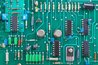 [/vc_column_text][/vc_column][vc_column width=”3/4″][vc_column_text]Circuit boards are the foundation of most electronics on the market. When building them, we must select the right type of circuit board components to achieve desired performance.
That’s why knowing their workings is critical to understanding electronics and assembling your own.
The following guide will show you how to choose the right circuit board components for your intended use. [/vc_column_text][/vc_column][/vc_row][vc_row][vc_column][vc_column_text]
Types of Circuit Board Components
Various components make up circuit boards, which vary in complexity. Here is an overview of the most common types of circuit board components:
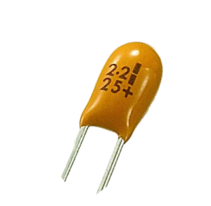
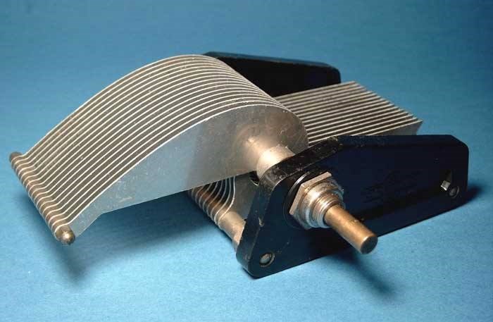
1. Passive Components
[/vc_column_text][/vc_column][/vc_row][vc_row content_placement=”middle”][vc_column width=”1/3″][vc_column_text]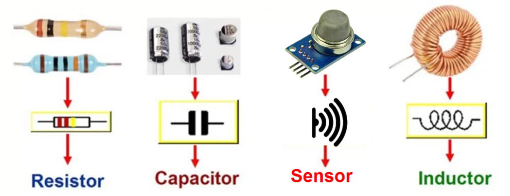 [/vc_column_text][/vc_column][vc_column width=”2/3″][vc_column_text]Passive Components are those components that do not have a power source. They consume energy from the power source but do not generate voltage or current. Passive components may be made of semiconductors or insulators.[/vc_column_text][/vc_column][/vc_row][vc_row][vc_column][vc_column_text]
Purpose
There are three purposes for passive components:
- Reducing the current through a circuit increases its resistance.
- Circuit voltage limitation.
- Storing energy in the form of an electric field or magnetic field.
Common Materials
- Copper
- Nickel
- Silver
- Palladium
Advantages
The advantages of passive circuit board components include the following:
- These are relatively inexpensive.
- Lightweight and small in size.
- One chip or a board can integrate it with other components.
- Due to their low losses, passive components can be used over a wide range of frequencies (10 Hz to 100 kHz), unlike active devices.
Applications
- Power supplies: Used in rectifiers, capacitors, and filters.
- Audio amplifiers: Used in filters, capacitors, and inductors.
- Filters: Used in capacitors, inductors, and resistors to remove unwanted frequencies.
- Medical devices: Used in sensors and monitoring equipment.
- Aerospace technology: Used in sensors, navigation systems, and communication equipment.
- Industrial automation: Used in sensors, switches, and control systems.
Common Types
The most common types of passive components include:
- Resistors are used to limit current flow through a circuit by producing heat or resistance when current passes through them.
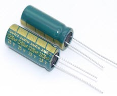
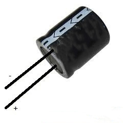
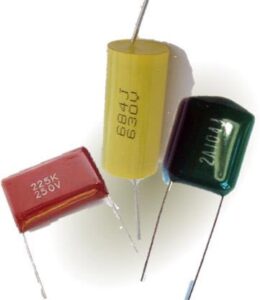
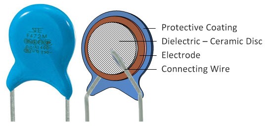
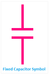
- Capacitors store electrical energy by building up an opposite charge on two conductive plates separated by an insulator, such as air or plastic.
- Inductors generate an electromagnetic field around themselves when current passes through them.
[/vc_column_text][/vc_column][/vc_row][vc_row][vc_column][vc_column_text]
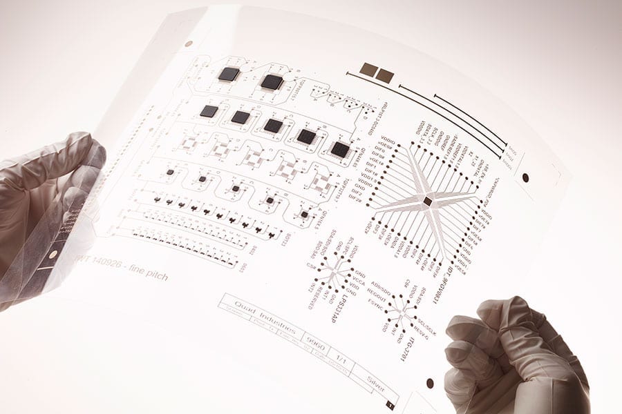
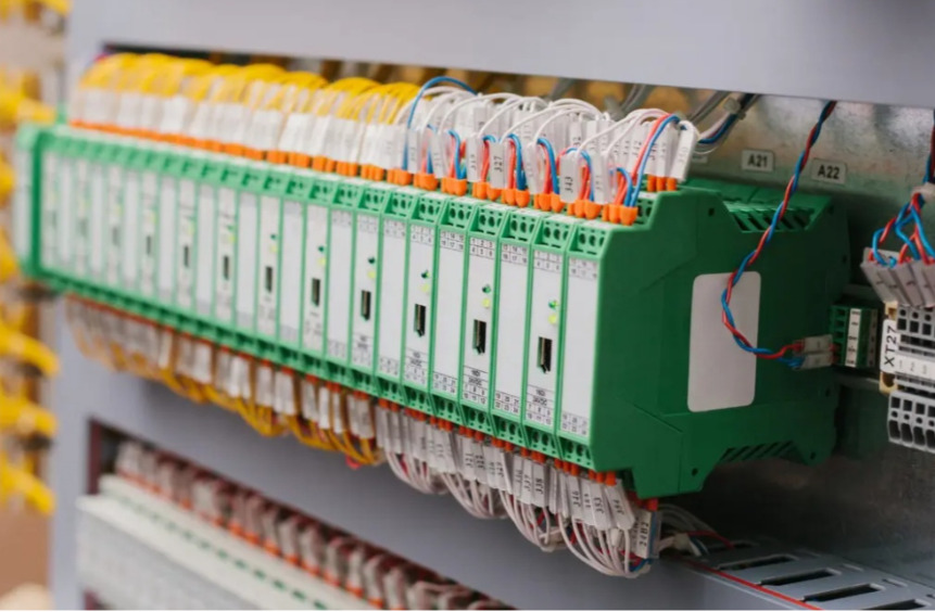
2. Active Components
[/vc_column_text][vc_row_inner][vc_column_inner width=”1/3″][vc_column_text]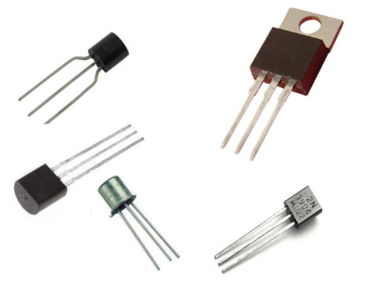 [/vc_column_text][/vc_column_inner][vc_column_inner width=”2/3″][vc_column_text]Active components are the parts of a circuit that do something. They can be transistors, diodes, or amplifiers.
In a simple circuit, an active component will have two terminals, a positive and a negative terminal. The positive terminal is usually marked on the component with a + sign, while the negative terminal is marked with a – sign. The other end of the component will also have a connection point called it’s base. This generally has three pins:
- one for the power supply,
- one for the ground,
- and one marked with an arrow pointing toward the + terminal.
Active components are used in most circuits to perform some function, such as amplification or switching.[/vc_column_text][/vc_column_inner][/vc_row_inner][/vc_column][/vc_row][vc_row][vc_column][vc_column_text]
Purpose
These devices amplify or switch electrical signals at high speeds. As well as changing the flow of electricity, they can switch between paths.
Common Materials
The materials used in the active components of a circuit board include:
- Copper foil or copper-clad laminate (Cu)
- Aluminum conductors are either directly plated onto the substrate or printed with a thick layer of copper using electroplating.
- Solder mask for covering exposed copper traces and pads to prevent corrosion and shorting
- Photoresist used as a protective film during etching and as a solder mask during soldering.
Advantages
These are some of the advantages of active components:
- Smaller than passive components
- Allow more space on the PCB for other components.
- Consume low power
- Energy conversion efficiency is high. So they can convert more energy into electricity than they consume from external sources.
Applications
The following are the applications of active components of the circuit board:
- Frequency control: Active components play an important role in frequency control. The device operates or functions at a certain frequency as a result of this.
- Amplification: Amplification is another application of active components. This occurs because it increases the signal’s amplitude.
- Voltage regulation: Another application of active component circuits is voltage regulation. Regardless of fluctuations in input voltage, it helps regulate the output voltage.
- Switching operation: Switching operation is yet another application of active component circuits wherein we use them to switch on/off a load that remains connected across an AC source (source).
Common Types
There are many different types of active components available today. Some examples include:
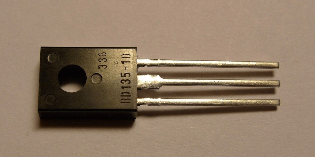
- Transistors: They can be used for amplification and switching. An emitter, a base, and a collector make up a transistor.
- Diodes: These allow current to flow only in one direction. They have three leads (anode, cathode, and gate).
Integrated Circuits (ICs): These silicon chips contain multiple transistors. Most computers use them to control the central processing unit (CPU).
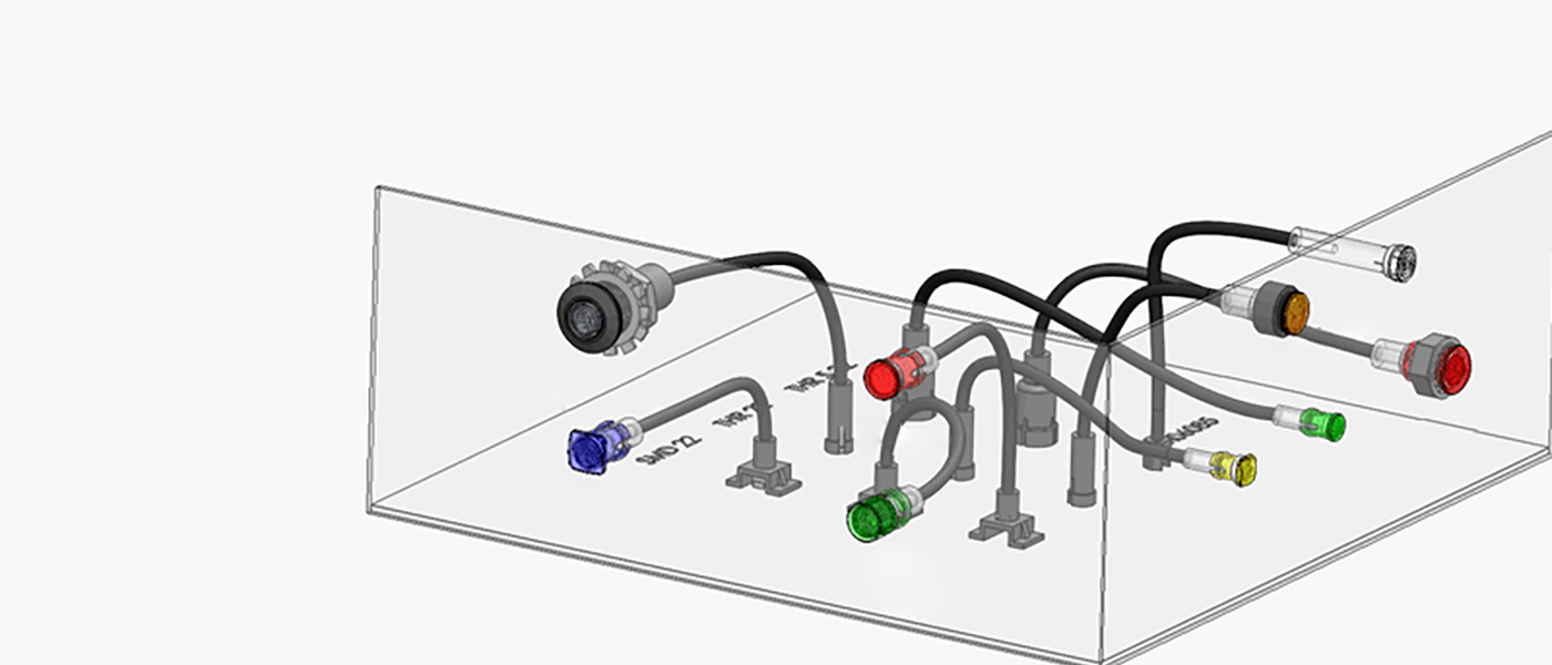
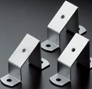
3. Electromechanical Components
[/vc_column_text][/vc_column][/vc_row][vc_row content_placement=”middle”][vc_column width=”1/3″][vc_column_text]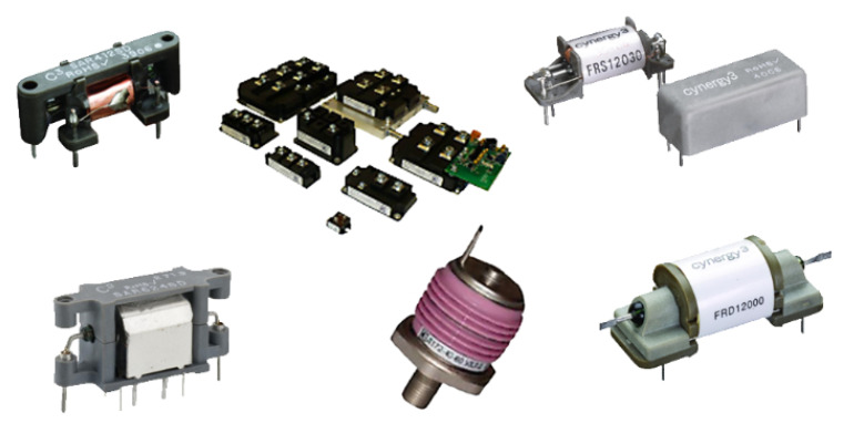 [/vc_column_text][/vc_column][vc_column width=”2/3″][vc_column_text]When a mechanical change, such as a motor rotating, is brought about by an electrical signal, the component is electromechanical. These typically generate a magnetic field using an electrical current, which creates a physical movement. This category includes relays and switches of every description. [/vc_column_text][/vc_column][/vc_row][vc_row][vc_column][vc_column_text]
Purpose
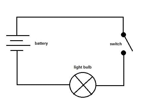
In a circuit board, electromechanical components act as conductive paths between two sides.
Common Materials
There are many different materials used in the manufacturing of electromechanical components. Here are a few of the most common:
- Metal alloys
- Plastics
- Rubber and elastomers
- Glass
Advantages
Electromechanical components have the following advantages:
- Have a high degree of precision in positioning and speed.
- Have low noise.
- A long service life and can last for years without maintenance or replacement.
- Easily installed and lightweight.
Applications
- Transducers: Sensors, microphones, and speakers use these devices to convert mechanical motion into electrical signals.
- Sensors: Temperature, pressure, and motion can be measured with these devices in a variety of applications, such as automotive, aerospace, and medical.
- Generators: Found in power plants, wind turbines, and hydroelectric plants, electromechanical generators convert mechanical energy to electricity.
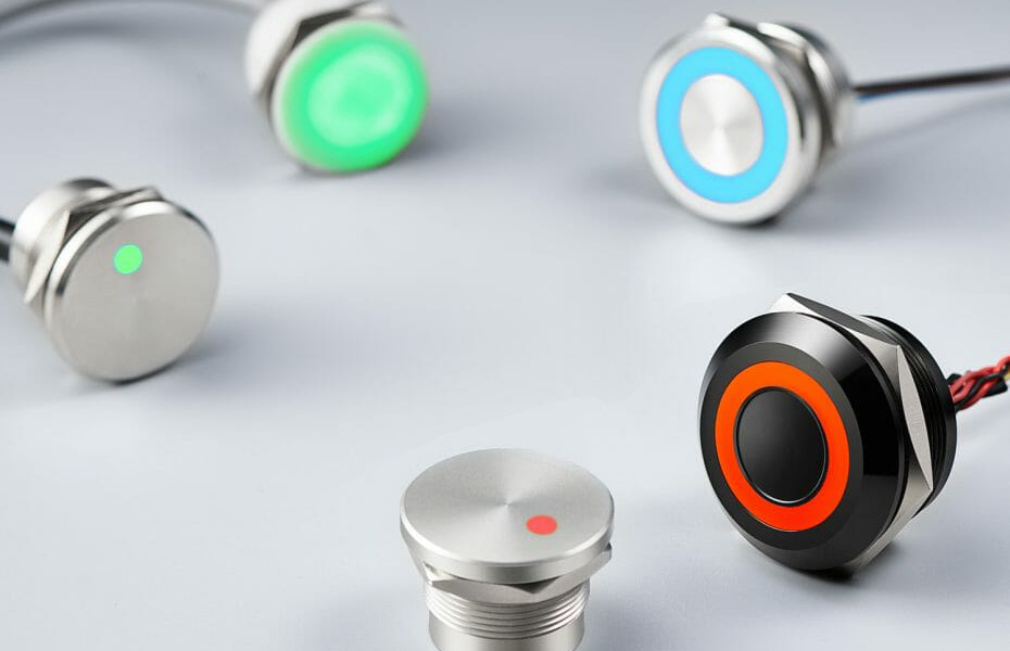
Common Types
Some types include:
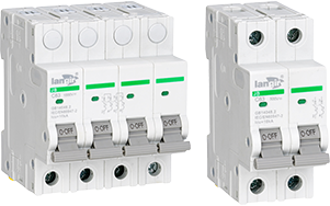
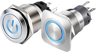
- Relays: Devices that allow a low voltage circuit to control a high voltage circuit, commonly used in power and industrial applications.
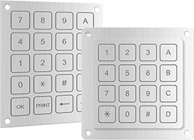
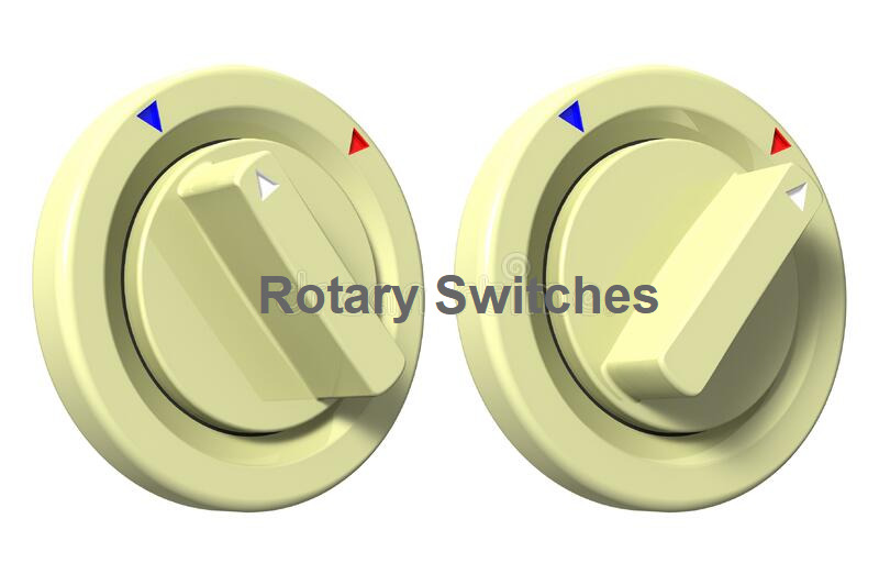
- Switches: Can be used to connect or disconnect electrical circuits and include pushbutton, toggle, rotary, and slide switches.
- Connectors: Connect two or more electrical circuits. Available in USB, audio, video, and power types. Electronic devices cannot function properly without them.
[/vc_column_text][/vc_column][/vc_row][vc_row][vc_column][vc_column_text]
How to Choose the Circuit Board Components?
The first thing you need to do is decide what you want your circuit board to do. Are you building a simple timer or an advanced sensor?
This will help narrow down the types of components that you need.
- Functionality: Choosing components that match the required functions of the circuit board.
- Size: Select components that fit within the physical dimensions of the board.
- Power: Choosing components that can handle the power requirements of the circuit.
- Availability: Ensuring that the components needed are easily accessible and in stock.
- Cost: Balancing the cost of the components with the project’s overall budget.
- Reliability: Select components known to be reliable and have a long lifespan.
- Manufacturer’s Reputation: When choosing parts for your circuit boards, look at how long they’ve been in business and how many products they’ve shipped successfully. For those seeking a dependable and experienced manufacturer of circuit board components, Langir is an excellent option.
Circuit Board Design and Layout
[/vc_column_text][/vc_column][/vc_row][vc_row content_placement=”middle”][vc_column width=”1/3″][vc_column_text]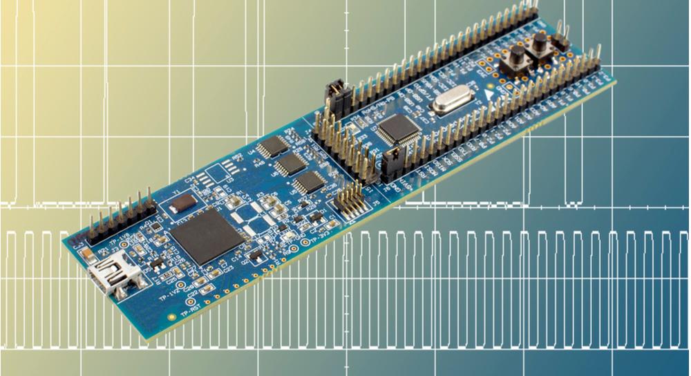 [/vc_column_text][/vc_column][vc_column width=”2/3″][vc_column_text]Selecting the right components for circuit board design is crucial for optimal performance, reliability, and cost-effectiveness. The proper component selection also ensures the compatibility and availability of the components.
It is essential to consult with an experienced provider for guidance in selecting the right components for your circuit board design.[/vc_column_text][/vc_column][/vc_row][vc_row][vc_column][vc_column_text]
Best Practices for Circuit Board Layout with Different Component Types
Here are some best practices for circuit board layout with different component types:
Passive Components:
- Place passive components near the IC or connector they are connected to.
- Group passive components, such as filtering or signal coupling, are used for the same function.
Active Components:
- Place active components in the center of the circuit board to minimize signal interference.
- Use decoupling capacitors close to active circuit board components to reduce noise.
Connectors:
- Place connectors at the edge of the circuit board for easy access.
- Orient connectors in a consistent direction to ensure proper alignment.
- Ensure proper spacing between connectors to prevent interference.
Power and Ground:
- Use a separate plane for power and ground to minimize noise.
- Power and ground traces are wide enough to handle the required current.
High-Frequency Components:
- Place high-frequency components in a location where they can minimize the effect of parasitic capacitance and inductance.
- Use short traces for high-frequency components to minimize signal loss.
- Use a dedicated ground plane to minimize signal interference.
[/vc_column_text][vc_row_inner][vc_column_inner width=”1/5″][/vc_column_inner][vc_column_inner width=”3/5″][vc_column_text]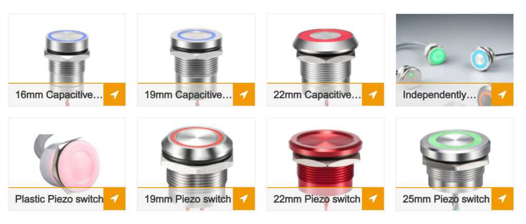 [/vc_column_text][/vc_column_inner][vc_column_inner width=”1/5″][/vc_column_inner][/vc_row_inner][/vc_column][/vc_row][vc_row][vc_column][vc_column_text]
Circuit Board Assembly
Circuit board assembly is populating a circuit board with electronic components to make a functioning electronic device. The process involves several steps, including component selection, printed circuit board (PCB) layout, and the assembly process.
Types of Assembly Methods
There are two primary methods of circuit board assembly:
Through-hole
[/vc_column_text][/vc_column][/vc_row][vc_row content_placement=”middle”][vc_column width=”1/3″][vc_column_text]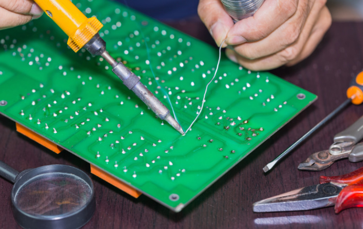 [/vc_column_text][/vc_column][vc_column width=”2/3″][vc_column_text]Through-hole assemblies are the most common and the simplest. They can be assembled by hand or by automated equipment.[/vc_column_text][/vc_column][/vc_row][vc_row][vc_column][vc_column_text]
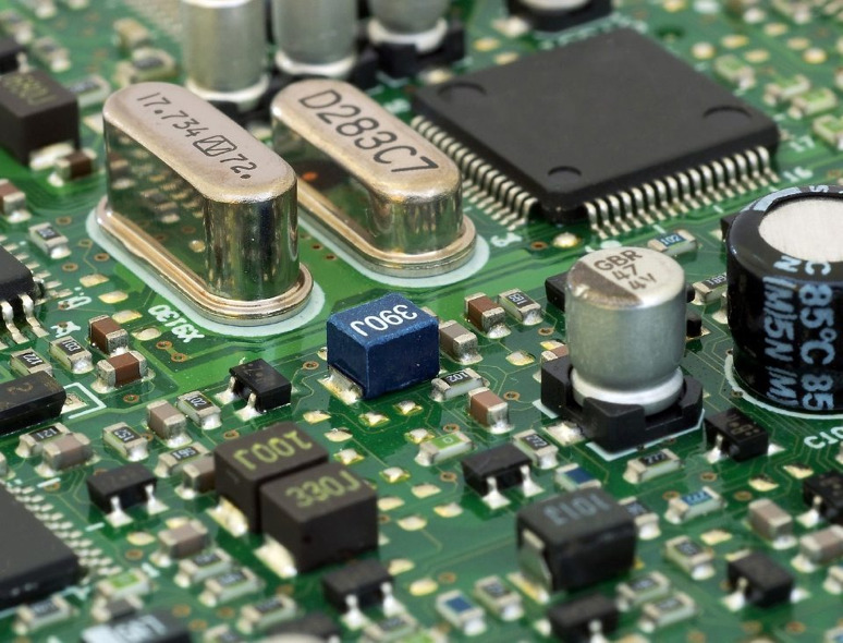
Surface-mount
[/vc_column_text][/vc_column][/vc_row][vc_row content_placement=”middle”][vc_column width=”1/3″][vc_column_text]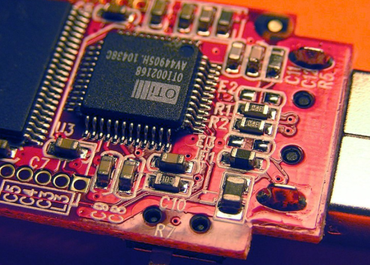 [/vc_column_text][/vc_column][vc_column width=”2/3″][vc_column_text]Surface-mount assemblies are more difficult to assemble because of their small size and narrow pitch between leads. They’re often soldered automatically using wave soldering or reflow soldering.
Composite testing components before assembly and avoiding thermal shock during soldering is critical for surface-mount assemblies because they have less tolerance for thermal stress than through-hole components.[/vc_column_text][/vc_column][/vc_row][vc_row][vc_column][vc_column_text]
Testing Components Before Assembly
Testing circuit board components before assembly ensures they meet specifications and function properly. Using this process prevents costly errors that may result in product failure.
Avoiding Thermal Shock During Soldering
[/vc_column_text][/vc_column][/vc_row][vc_row content_placement=”middle”][vc_column width=”1/3″][vc_column_text]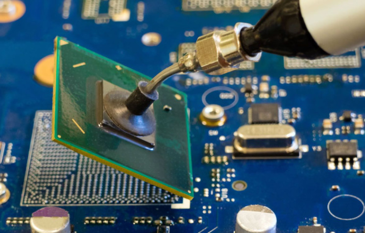 [/vc_column_text][/vc_column][vc_column width=”2/3″][vc_column_text]Thermal shock can occur during the soldering process when the component’s temperature changes too quickly. This can cause damage to the component or the PCB. To prevent thermal shock, the PCB and components should be heated and cooled gradually to reduce the risk of damage.[/vc_column_text][/vc_column][/vc_row][vc_row][vc_column][vc_column_text]
Soldering Techniques and Assembly Equipment
Soldering techniques and equipment include wave soldering, reflow soldering, and manual soldering. Depending on the volume of production and the type of components soldered, the equipment will vary.[/vc_column_text][/vc_column][/vc_row][vc_row][vc_column][vc_column_text]
Troubleshooting Circuit Board Components
Circuit board components can experience various issues, such as failure, damage, incorrect installation, and compatibility issues. Troubleshooting and diagnosing these issues requires knowledge of different component types and diagnostic tools.
Common Issues with Circuit Board Components
Circuit boards and their components are prone to the following problems:
- Failure: Overvoltage, overheating, or improper handling can cause circuit board components to fail.
- Damage: Components can get damaged during handling, assembly, or operation, causing circuit board failures.
- Incorrect installation: Issues such as polarity reversal or misalignment can arise due to incorrect installation.
- Compatibility issues: Some circuit board components may not be compatible with the PCB or other components.
Troubleshooting and Diagnosing Different Types of Components
Various diagnostic tools are available to troubleshoot issues with passive and active components, including multimeters, oscilloscopes, and logic analyzers. Tools like these identify the root cause, such as faulty components or broken traces.
Reworking Techniques
Reworking techniques involve repairing or replacing damaged components on a PCB. Techniques include desoldering, hot air rework stations, and soldering irons. It is essential to follow proper reworking techniques to prevent further damage to the PCB or components.[/vc_column_text][/vc_column][/vc_row][vc_row][vc_column][vc_column_text]
Future of Circuit Board Components
Automation, miniaturization, and artificial intelligence (AI) will influence future developments in circuit board components.
Smaller, more effective electronic components are required as the demand for more complex electronic devices rises. Nanotechnology plays a crucial role here. Nanotechnology uses materials measured in nanometers (nm) or billionths of a meter.
The benefits of nanoscale manufacturing techniques are numerous, including
- Smaller size-related improvements in performance and efficiency
- Improved durability and reliability due to fewer flaws
- And lower energy consumption.
AI systems have been developed for use in transportation, healthcare, and other industries. Over the past several years, AI-based systems have been used increasingly for sophisticated tasks like image identification, object recognition, speech recognition, and translation without requiring human intervention. Offers insights into enormous datasets by identifying patterns humans cannot understand.
Equipment size is getting smaller, yet performance is accelerating faster than ever, thanks to the miniaturization trend. Due to this tendency, producers may now produce high-performance products at the lowest possible cost.[/vc_column_text][/vc_column][/vc_row][vc_row][vc_column][vc_column_text]
Conclusion
Proper component selection, design, and assembly are crucial for successfully operating circuit board components. To ensure that your circuit boards meet these requirements, it’s essential to consult with a reputable and experienced provider like Langir.
With their expertise in panel switches, control panels, and circuit protection, Langir can assist you in every stage of the circuit board development process. [/vc_column_text][vc_row_inner][vc_column_inner width=”1/5″][/vc_column_inner][vc_column_inner width=”3/5″][vc_column_text][/vc_column_text][/vc_column_inner][vc_column_inner width=”1/5″][/vc_column_inner][/vc_row_inner][/vc_column][/vc_row][vc_row][vc_column][vc_zigzag]
 [/vc_column_text][/vc_column_inner][vc_column_inner width=”1/4″][vc_column_text]
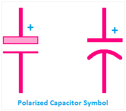 [/vc_column_text][/vc_column_inner][vc_column_inner width=”1/4″][vc_column_text]
 [/vc_column_text][/vc_column_inner][vc_column_inner width=”1/4″][vc_column_text]
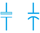 [/vc_column_text][/vc_column][vc_column width=”1/4″][vc_column_text]
 [/vc_column_text][/vc_column][vc_column width=”1/4″][vc_column_text]
 [/vc_column_text][/vc_column][vc_column width=”1/4″][vc_column_text]
 [/vc_column_text][/vc_column][vc_column width=”1/4″][vc_column_text]
 [/vc_column_text][/vc_column][vc_column width=”1/4″][vc_column_text]
 [/vc_column_text][/vc_column][vc_column width=”1/4″][vc_column_text]
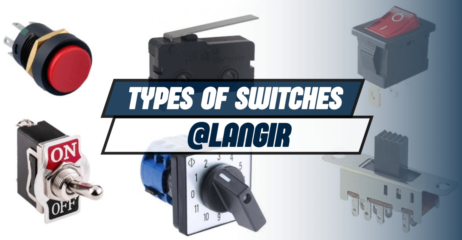
 [/vc_column_text][/vc_column][vc_column width=”2/3″][vc_column_text css=””]
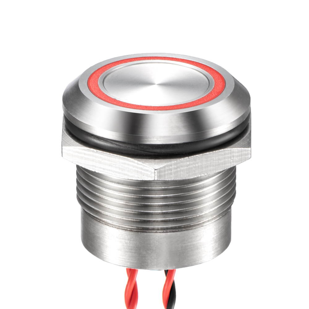 [/vc_column_text][/vc_column][vc_column width=”2/3″][vc_column_text css=””]
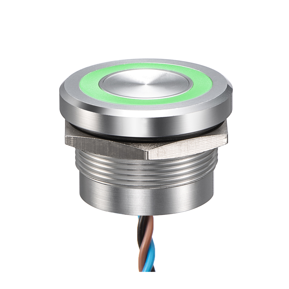 [/vc_column_text][/vc_column][/vc_row][vc_row content_placement=”middle”][vc_column width=”1/3″][vc_column_text]
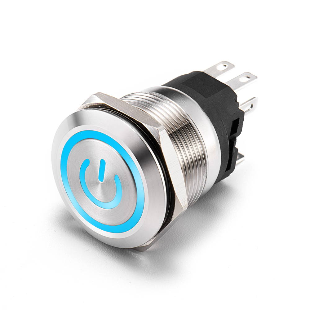 [/vc_column_text][/vc_column][vc_column width=”2/3″][vc_column_text css=””]
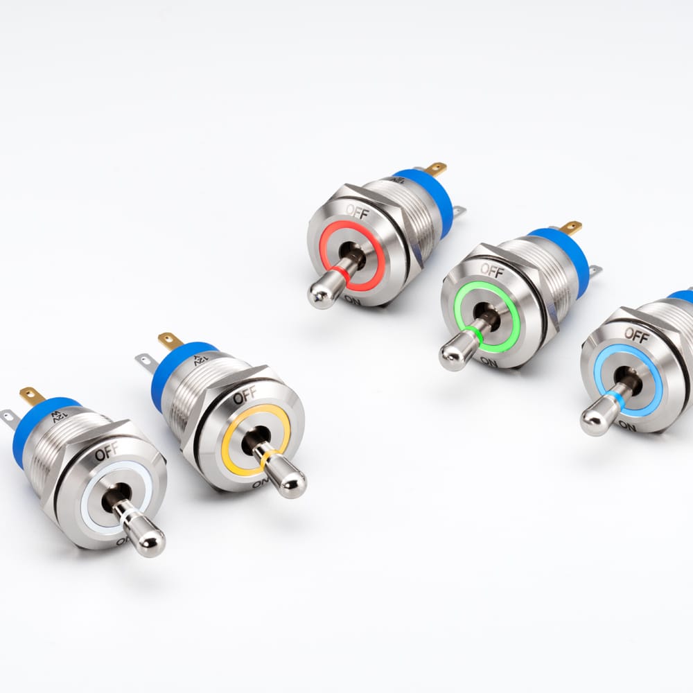
 [/vc_column_text][/vc_column][vc_column width=”2/3″][vc_column_text css=””]
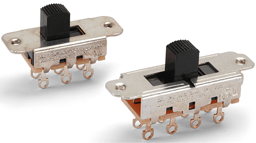 [/vc_column_text][/vc_column][/vc_row][vc_row content_placement=”middle”][vc_column width=”1/3″][vc_column_text]
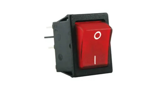 [/vc_column_text][/vc_column][vc_column width=”2/3″][vc_column_text css=””]
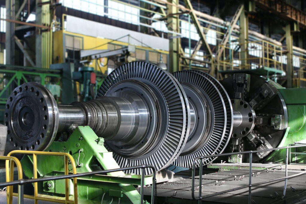


 [/vc_column_text][/vc_column][vc_column width=”2/3″][vc_column_text css=””]
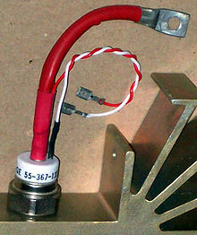 [/vc_column_text][/vc_column][/vc_row][vc_row content_placement=”middle”][vc_column width=”1/3″][vc_column_text]
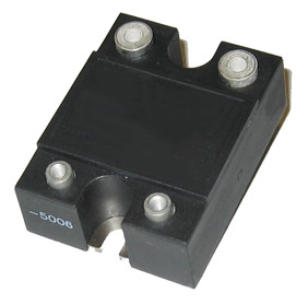 [/vc_column_text][/vc_column][vc_column width=”2/3″][vc_column_text css=””]
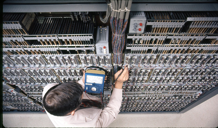

 [/vc_column_text][/vc_column_inner][vc_column_inner width=”1/5″][/vc_column_inner][/vc_row_inner][/vc_column][/vc_row][vc_row][vc_column][vc_column_text]
 [/vc_column_text][/vc_column][vc_column width=”2/3″][vc_column_text]
 [/vc_column_text][/vc_column][vc_column width=”2/3″][vc_column_text]
 [/vc_column_text][/vc_column][vc_column width=”2/3″][vc_column_text]
 [/vc_column_text][/vc_column][vc_column width=”2/3″][vc_column_text]

 [/vc_column_text][/vc_column][vc_column width=”2/3″][vc_column_text]
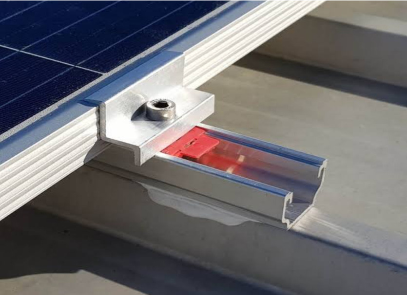 [/vc_column_text][/vc_column][vc_column width=”2/3″][vc_column_text]
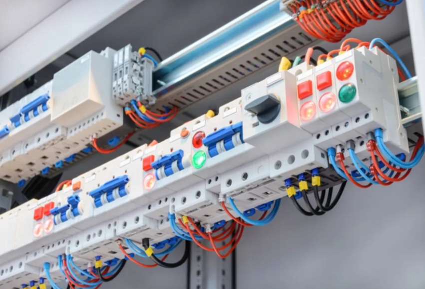 [/vc_column_text][/vc_column][vc_column width=”2/3″][vc_column_text]
 [/vc_column_text][/vc_column][vc_column width=”2/3″][vc_column_text]
 [/vc_column_text][/vc_column][vc_column width=”2/3″][vc_column_text]