
[vc_row][vc_column][vc_column_text]
Ensuring Safety with E-Stop Switch | E-stop Button in 2024
[/vc_column_text][vc_single_image image=”8531″ img_size=”1200×350″ alignment=”center”][/vc_column][/vc_row][vc_row][vc_column][vc_column_text]In today’s fast-paced world, safety is paramount across various industries. To ensure smooth business processes, the e-stop switch is truly a game changer. It is a key contributor to machinery and employee safety. During emergency situations, these kill switches provide an immediate means to shut down potentially hazardous operations. It prevents further risks to personnel, equipment, and the surrounding environment.
This comprehensive blog provides you with an in-depth understanding of estop meaning along with its various aspects. Stay tuned with us till the end of the blog to choose the right device for your industrial or commercial setting.[/vc_column_text][/vc_column][/vc_row][vc_row][vc_column][vc_column_text]
What is E-Stop Switch Definition?
[/vc_column_text][/vc_column][/vc_row][vc_row content_placement=”middle”][vc_column width=”1/3″][vc_column_text]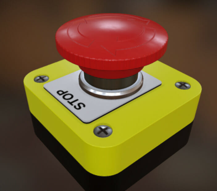 [/vc_column_text][/vc_column][vc_column width=”2/3″][vc_column_text]E-stop switch is a safety device that provides effective and quick intervention in emergency scenarios. When activated, this emergency stop button halts the operations by interrupting the power or control signals to the equipment. By rapidly bringing processes to a controlled manner, it prevents accidents, injuries, or potential damages.
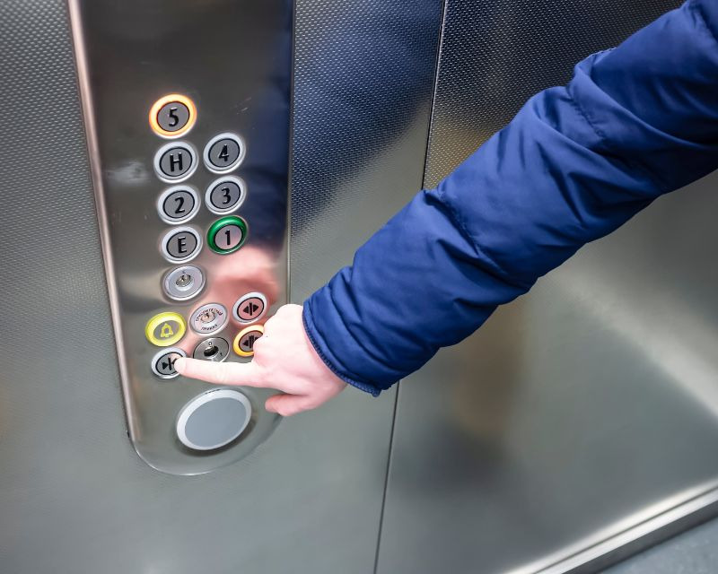
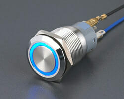
You might be wondering what an e-stop switch looks like. An emergency stop switch is designed in a visible color, label, and shape to make it highly recognizable in alarming situations. To make it easily accessible for the operators, these switches are positioned strategically within the reach of personnel. Their robust construction is standardized to ensure a quick response to perilous situations.[/vc_column_text][/vc_column][/vc_row][vc_row][vc_column][vc_column_text]
What is the Purpose of an E-Stop Switch?
The primary function of an e-stop switch is to safeguard against incidents that can occur due to machinery errors, operator faults, or unforeseen events. When normal procedure fails to alleviate an immediate threat, the e-stop switch acts as a last line of defense. By quickly stopping the operations, it prioritizes the employee’s safety working with or around the equipment. It provides swift and decisive shutdowns in critical situations to mitigate potential harm.[/vc_column_text][/vc_column][/vc_row][vc_row][vc_column][vc_column_text]
How does the Emergency Stop Switch Work?
The functionality of the emergency stop switch is rooted in its intuitive design. The core principle of e stop circuit is to break the electrical circuit that powers the machinery or equipment. To understand how it accomplishes this role, let’s have an overview of its working.[/vc_column_text][/vc_column][/vc_row][vc_row][vc_column][vc_column_text]
Electrical Interruption
When the button is pressed, it physically opens an electrical contact within the switch. This interruption breaks the circuit that halts the flow of current to critical elements such as motors, actuators, or control systems. To initiate immediate system closure, a series of actions occur to cut off the power, preventing further operations.
Activating Safety Relays & Control Logic
To elevate the functioning of an e-stop switch, modern industrial setups deploy safety relays and control logic. They act as intermediaries between the e-stop switch and the machinery’s control circuit to provide an additional layer of monitoring. When the e-stop button is pressed, the safety relays detect the change and initiate a ‘safe state’ reliable response. They ensure that safety interlocks and contribute to rapid shutdowns of the operations.
Latching Systems
E-stop systems also incorporate latching mechanisms to ensure that the button remains in the off position until the situation is addressed. It helps to avoid accidental reactivation of the machinery. To resume machine operations, the e-stop switch should be manually rotated or turned on.[/vc_column_text][vc_row_inner][vc_column_inner width=”1/5″][/vc_column_inner][vc_column_inner width=”3/5″][vc_column_text]
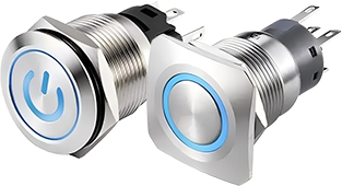
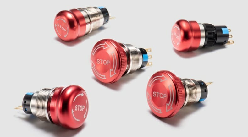
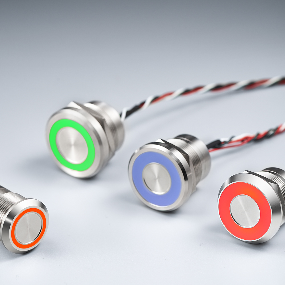
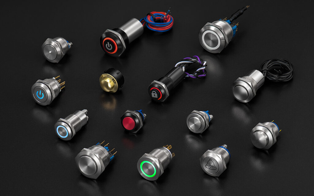
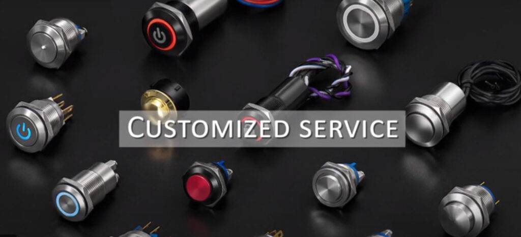
 E-stop Switch Buttons at Langir
[/vc_column_text][/vc_column_inner][vc_column_inner width=”1/5″][/vc_column_inner][/vc_row_inner][/vc_column][/vc_row][vc_row][vc_column][vc_column_text]
How to wire e stop button?
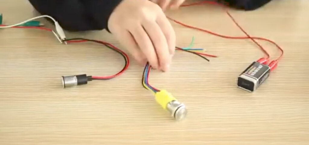
Wiring an emergency stop button requires careful attention to detail and compliance with safety practices. Proper wiring ensures that the emergency stop button can effectively interrupt the power supply to prevent potential hazards. Here’s a step-by-step guide on how to wire e stop button:
- First, gather all the essential materials which are needed to connect the e-stop system to your control devices. You may require an e-stop switch, control panel, wiring cables, screwdrivers, and related equipment.
- Turn off all the power sources to the machinery to avoid any accidents during the wiring process.
- Determine the wiring configuration. Commonly, the e-stop switch is connected in series with the control circuit of the machinery.
- Mount the emergency stop button in an appropriate location that is accessible to the operators. It usually sits within an electrical circuit and allows the current to pass through the button. Make sure that it is installed before the control breaker and after the on/off switches.
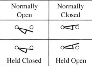
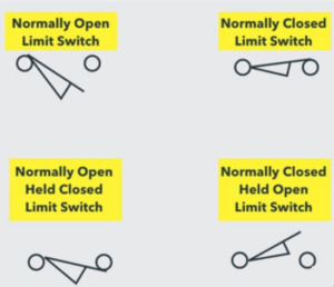
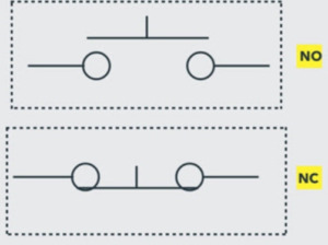
- Wires are now connected to their normally open (NO) terminals. These are the terminals that open the circuit when the button is pressed.
- Connect the other ends of the wiring cable in line with the control circuit of the equipment.
- After wiring, perform a test to ensure that it functions as intended. You can also label the e-stop switch for easy recognition.
[/vc_column_text][/vc_column][/vc_row][vc_row][vc_column][vc_column_text]
Different Types of E-Stop Switch
When you step into the market, you will find a variety of options. The choice of the e-stop switch depends on your specific needs, the type of machinery, and the safety regulations in your industry. Let’s get into some of the common types of switches in the following.
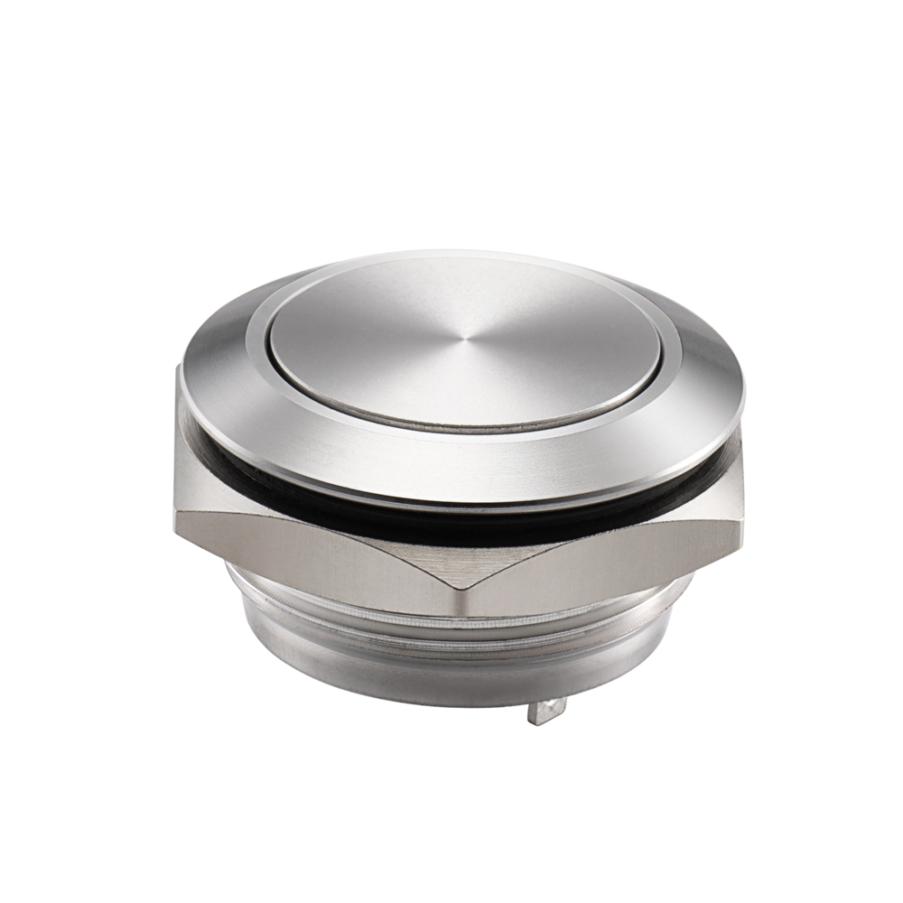
Mushroom-Head E-Stop Switch
[/vc_column_text][/vc_column][/vc_row][vc_row content_placement=”middle”][vc_column width=”1/3″][vc_column_text]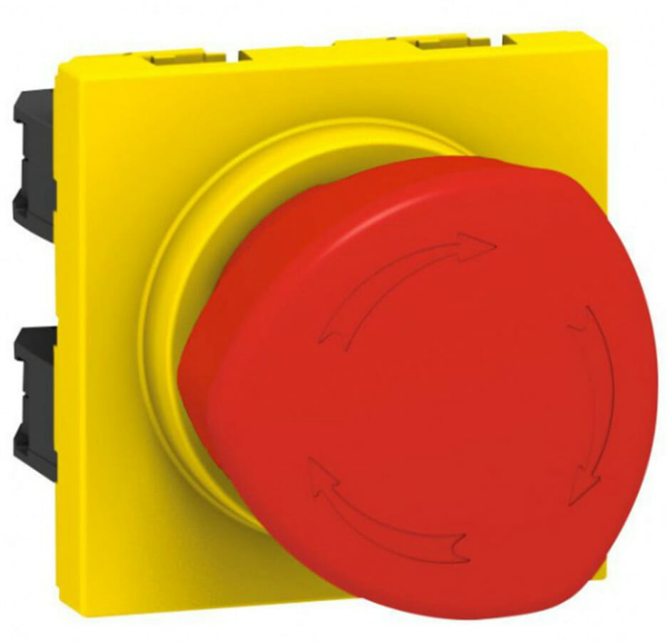 [/vc_column_text][/vc_column][vc_column width=”2/3″][vc_column_text]These safety buttons feature a large mushroom-shaped head, mostly red in color. Its intuitive design makes it easy to push it during an emergency. Due to its convenient operation, it is one of the most commonly used switches in industries.[/vc_column_text][/vc_column][/vc_row][vc_row][vc_column][vc_column_text]
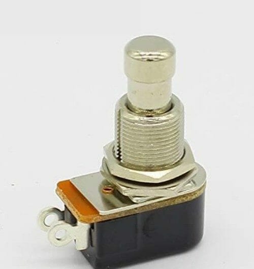
Pull-Push Release
[/vc_column_text][/vc_column][/vc_row][vc_row content_placement=”middle”][vc_column width=”1/3″][vc_column_text]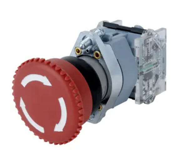 [/vc_column_text][/vc_column][vc_column width=”2/3″][vc_column_text]This type of button combines a pulling and a pushing action to activate and reset the e-stop switch. To activate it, you pull the button out, breaking the circuit and shutting down the machinery. To reset it, you push the button back in, allowing the equipment to restart once the emergency situation is over. This design prevents accidental resetting, ensuring that the machinery remains stopped until a deliberate reset action is taken.[/vc_column_text][/vc_column][/vc_row][vc_row][vc_column][vc_column_text]
Twist Release
[/vc_column_text][/vc_column][/vc_row][vc_row content_placement=”middle”][vc_column width=”1/3″][vc_column_text]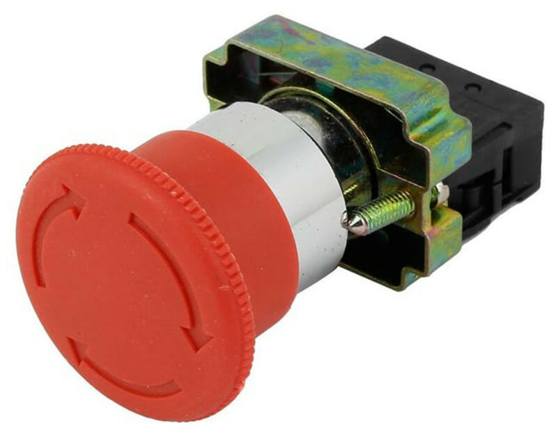 [/vc_column_text][/vc_column][vc_column width=”2/3″][vc_column_text]The twist release switch requires you to rotate the button to activate the emergency stop. To reset it, you also need to twist it back. This mechanism adds an extra layer of safety by making it harder to reset accidentally. It’s commonly used in situations where inadvertent reset could be hazardous.[/vc_column_text][/vc_column][/vc_row][vc_row][vc_column][vc_column_text]
Key Release
[/vc_column_text][/vc_column][/vc_row][vc_row content_placement=”middle”][vc_column width=”1/3″][vc_column_text]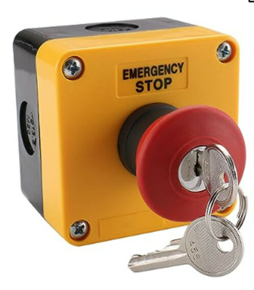 [/vc_column_text][/vc_column][vc_column width=”2/3″][vc_column_text]This e-switch type switch uses a key to activate and reset the emergency stop function. Inserting the key and turning it activates the e-stop, immediately stopping the machinery. To reset the system and resume operations, you turn the key back to its original position. This type of switch prevents unauthorized personnel from restarting the equipment.[/vc_column_text][/vc_column][/vc_row][vc_row][vc_column][vc_column_text]
Importance of e-stop Switch in Safety
The role of e-stop switches cannot be overstated. Its importance in protecting human lives and equipment is phenomenal. Here are some benefits of employing switches in your business settings.
- Immediate Response to Hazards: The primary role of the emergency stop button is to offer an instant means of stopping machinery in emergency scenarios. Whether due to equipment malfunction, employee error, or unexpected events, the e-stop switch can swiftly interrupt operations and prevent hazardous scenarios.
- Safety from Injuries and Damage: By halting operations promptly, the estop button reduces the likelihood of injuries and fatalities. It prevents individuals from being caught in moving parts, crushed, or injured.
- Protection of Personnel and Equipment: The estop switch safeguards both operators and equipment from harm. It prevents accidents and alleviates the chances of costly damage to machinery, tools, and production processes. By stopping operations instantaneously, it mitigates the probability of mechanical failure or other forms of damage that could lead to downtime and repair expenses.
- Creating a Safety Culture: E-stop switches contribute to the development of a safety-focused organizational culture. When workers see that their well-being is at the top, it encourages a mindset of responsibility and proactive safety practices. Adherence to safety standards ensures a secure working environment and a commitment to legal and ethical responsibilities.
[/vc_column_text][/vc_column][/vc_row][vc_row][vc_column][vc_column_text]
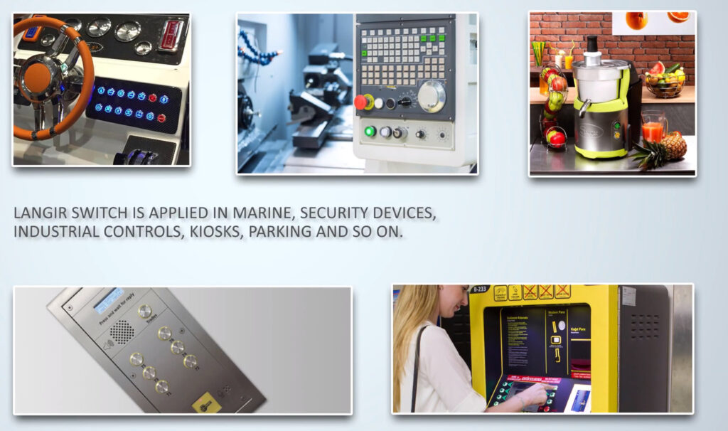
Where is the Emergency Stop Switch Used?
Emergency stop switch is deployed in a variety of industries and public facilities where safety is the main concern. Its widespread use across industries underscores its importance in providing safer working conditions. Commonly, these buttons are used in the following ways:
Manufacturing and Industrial Settings
E-stop switches are highly used in production plants and industrial settings. They can be employed in several types of machinery, including cranes, bulldozers, excavators, and robotic systems. In these settings, emergency stop buttons are crucial for quickly shutting perilous processes to prevent accidents and injuries.
Automation and Robotics
With the integration of estop buttons into automated systems, you can ensure that the automatic machines can be halted in grave situations. This is vital for alleviating collisions, malfunctions, and other potential damages that could arise during the operation of autonomous equipment.
Transportation and Vehicles
Emergency safety buttons are present in vehicles, trains, and other forms of transportation. They allow operators to immediately stop the vehicle’s functions ensuring the safety of passengers, crew, and pedestrians.
Medical Equipment
Medical equipment, such as MRI machines, surgical robots, and anesthesia systems, often feature e-stop buttons. These switches enable medical professionals to halt equipment swiftly if patient safety is compromised.[/vc_column_text][/vc_column][/vc_row][vc_row][vc_column][vc_column_text]
E-stop Requirements
E-stop switches are subject to various standards to ensure their adequate functioning. These requirements help guarantee that estop buttons are properly designed, installed, and maintained. Some of the following requirements are presented in the European standard EN 418 and international standard ISO13850.
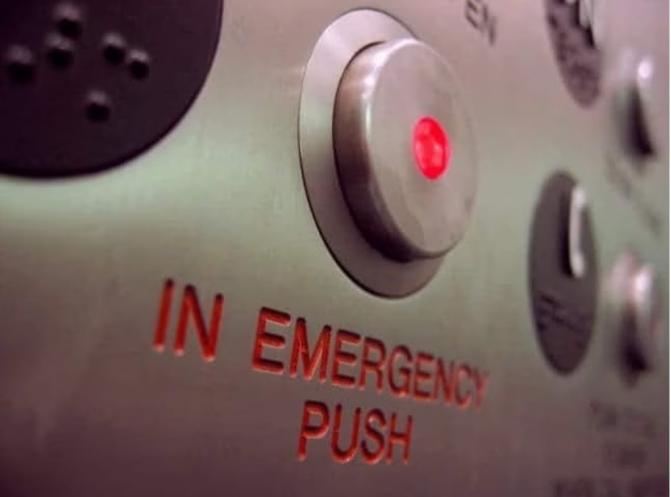
- An emergency stop switch must be extremely visible in terms of appearance to be used effectively in stress.
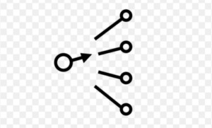
- To make it easy to push, the button should have a mushroom-shaped head in bright red color with the estop symbol of an arrow. The mushroom heads are commonly used in sizes 29, 30, 40, and 60 mm.
- There must be a self-latching mechanism to reactivate the machine operations
- For equipment to restart, electrical contacts must be released with a twist, pull, or key.
- E-Stop buttons must provide an immediate and complete shutdown of machinery.
- They should be placed in a conspicuous location to ensure quick response during emergencies.
- E-stop buttons should be compatible with the control systems of the machinery or equipment they are connected to.
- Regular functional testing and maintenance of E-Stop buttons are essential to ensure their reliability.
[/vc_column_text][/vc_column][/vc_row][vc_row][vc_column][vc_column_text]
How to Choose the Right Emergency Stop Button?
Choosing the right emergency stop button is essential for ensuring smooth workflows. While selecting a suitable safety device, take the following things into consideration.
Understand your Needs
Before delving into the right product, you need to specify the machinery that requires an emergency safety button. Not all the equipment needs an estop button. So, first, do a risk assessment of the machine and then go for the e-stop switch if needed.
Know the Regulations
Familiarize yourself with relevant safety regulations, standards, and guidelines in your industry or region. This will help you acknowledge the specific requirements for E-Stop buttons.
Type of Actuation
Based on the operator’s convenience, choose the right type of actuation. You can go for pull, push, key-release, or twist mechanisms accordingly.
Visibility and Accessibility
While choosing the right product, make sure that it is highly visible for easy recognition. You can use mushroom shaped estop systems with redheads mounted on yellow backgrounds as per standards. Also, locate them in places where it’s easy to access them in stressful situations.
Compatibility
Every emergency button is not suitable for all types of machinery. So, go for the e-stop switch that is compatible with the control system of your business equipment.
Environment Considerations
Moreover, if you need to use your machinery in an outdoor environment, select the safety button, which can resist harsh climate changes. Look for the e-stop buttons with water-resistant features.[/vc_column_text][vc_row_inner][vc_column_inner width=”1/5″][/vc_column_inner][vc_column_inner width=”3/5″][vc_column_text]
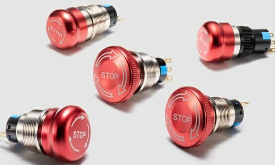
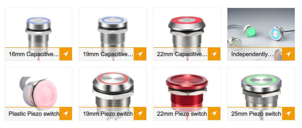
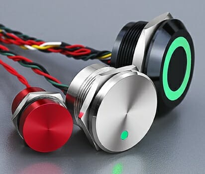
E-stop Switch Buttons at Langir
[/vc_column_text][/vc_column_inner][vc_column_inner width=”1/5″][/vc_column_inner][/vc_row_inner][/vc_column][/vc_row][vc_row][vc_column][vc_column_text]
FAQs
Q1: What’s the Difference Between the Push Button And the Emergency Stop Button?
A push button is used to start the machine operations or switch modes. But an emergency stop button is specified to stop the machinery during emergency situations.
Q2: Why is the Mushroom Head of the e-stop button Preferred?
According to IEC standards and safety requirements, the e-stop button must be visible and easy to use by operators with a single hand. For that purpose, a mushroom head is the best choice.
Q3: Can Emergency Stop Switch Prevent All Types of Accidents?
Emergency stop switches can significantly alleviate the risk of accidents. But you may need proper training, regular maintenance, and adherence to safety protocols for comprehensive protection.
Q4: Can E-stop Buttons be used remotely?
Yes, wireless e-stop buttons are available in the market that can be employed remotely. They are suitable for situations in which you need to stop equipment from a distance.
Q5: Can I install e-stop buttons Myself?
If you have an experience with electrical work, you can wire the emergency stop switches yourself. But it’s always recommended to have professional support for complex setups.[/vc_column_text][/vc_column][/vc_row][vc_row][vc_column][vc_column_text]
Conclusion
In short, e-stop switch stands as a paramount safety measure across industries. This immersive technology offers optimized control over the equipment. If you are looking for a reliable product, connect with Langir. We are a leading manufacturer of high-quality emergency stop switches. Why wait? Send your inquiry now![/vc_column_text][vc_zigzag]
[/vc_column][/vc_row][vc_row][vc_column][vc_zigzag][/vc_column][/vc_row]
 [/vc_column_text][/vc_column_inner][/vc_row_inner][/vc_column][/vc_row][vc_row content_placement=”middle”][vc_column width=”1/3″][vc_column_text css=””]


 [/vc_column_text][/vc_column_inner][vc_column_inner width=”1/5″][/vc_column_inner][/vc_row_inner][/vc_column][/vc_row][vc_row][vc_column][vc_column_text]When it comes to

 [/vc_column_text][/vc_column_inner][vc_column_inner width=”1/5″][/vc_column_inner][/vc_row_inner][/vc_column][/vc_row][vc_row][vc_column][vc_column_text]
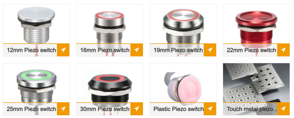

 [/vc_column_text][/vc_column_inner][vc_column_inner width=”1/5″][/vc_column_inner][/vc_row_inner][/vc_column][/vc_row][vc_row][vc_column][vc_column_text]Parking meter push button switches play a crucial role in modern parking systems, providing users with a convenient and intuitive way to pay for parking. These switches are designed to withstand the rigors of daily use while ensuring accurate and reliable functionality. In this article, we will explore the working principles of
 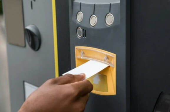 [/vc_column_text][/vc_column_inner][vc_column_inner width=”1/5″][/vc_column_inner][/vc_row_inner][/vc_column][/vc_row][vc_row][vc_column][vc_column_text]
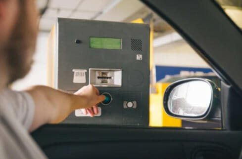 [/vc_column_text][/vc_column_inner][vc_column_inner width=”1/5″][/vc_column_inner][/vc_row_inner][/vc_column][/vc_row][vc_row][vc_column][vc_column_text]


 [/vc_column_text][/vc_column_inner][vc_column_inner width=”1/4″][vc_column_text]
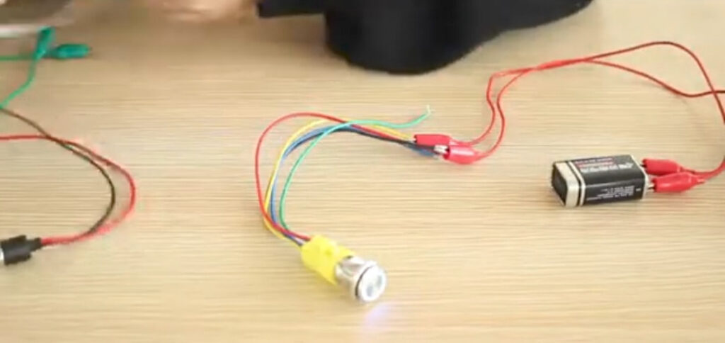 [/vc_column_text][/vc_column_inner][vc_column_inner width=”1/4″][vc_column_text]
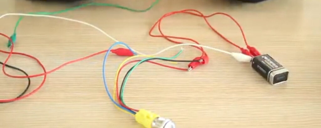 [/vc_column_text][/vc_column_inner][vc_column_inner width=”1/4″][vc_column_text]
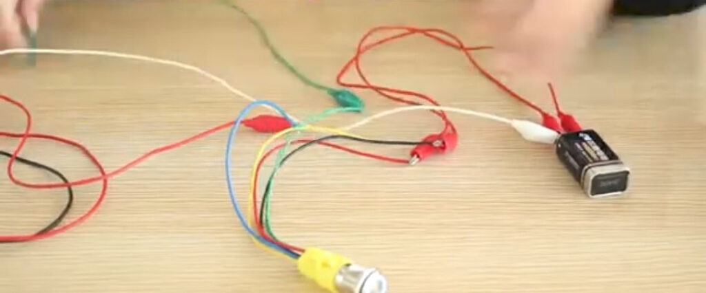 [/vc_column_text][/vc_column_inner][vc_column_inner width=”1/4″][vc_column_text]
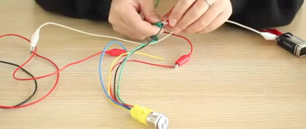 [/vc_column_text][/vc_column_inner][vc_column_inner width=”1/4″][vc_column_text]
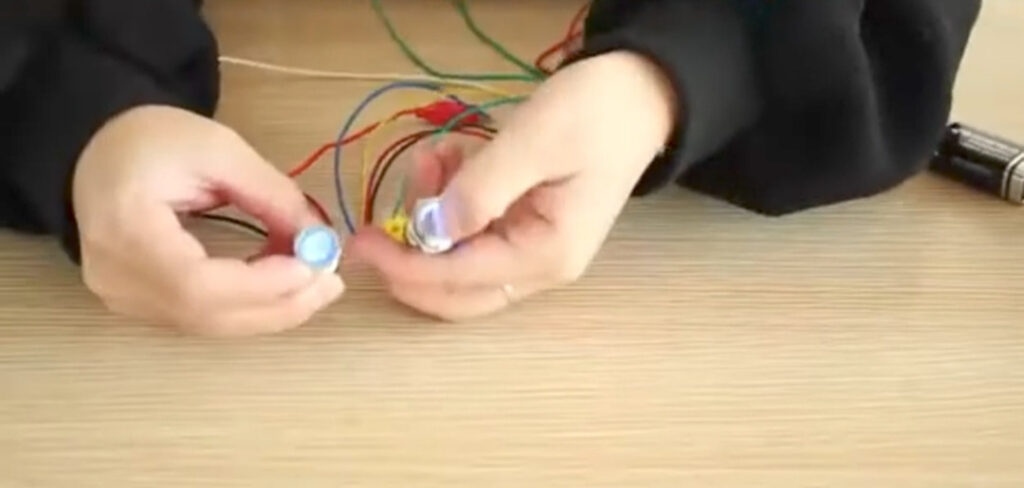 [/vc_column_text][/vc_column_inner][vc_column_inner width=”1/4″][vc_column_text]
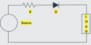
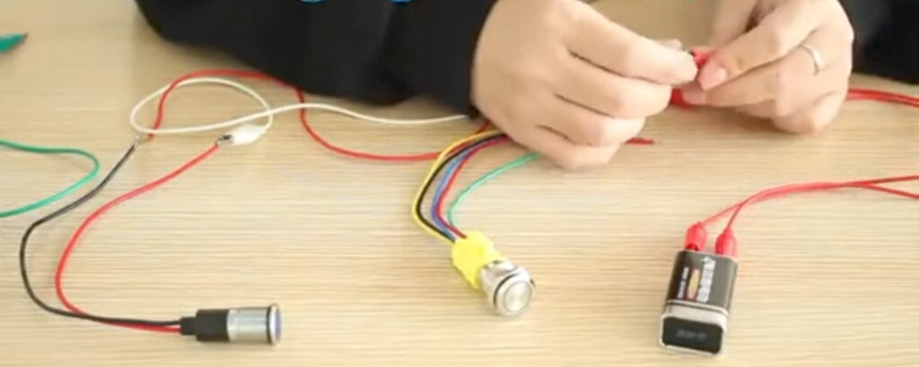 [/vc_column_text][/vc_column_inner][vc_column_inner width=”1/4″][vc_column_text css=””]Step 1: Link the Power Supply
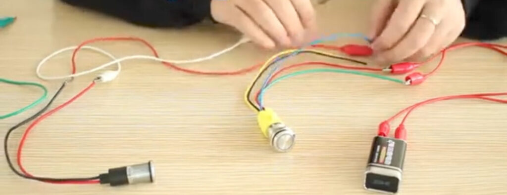 [/vc_column_text][/vc_column_inner][vc_column_inner width=”1/4″][vc_column_text css=””]Step 2: Connect One Side of the Device
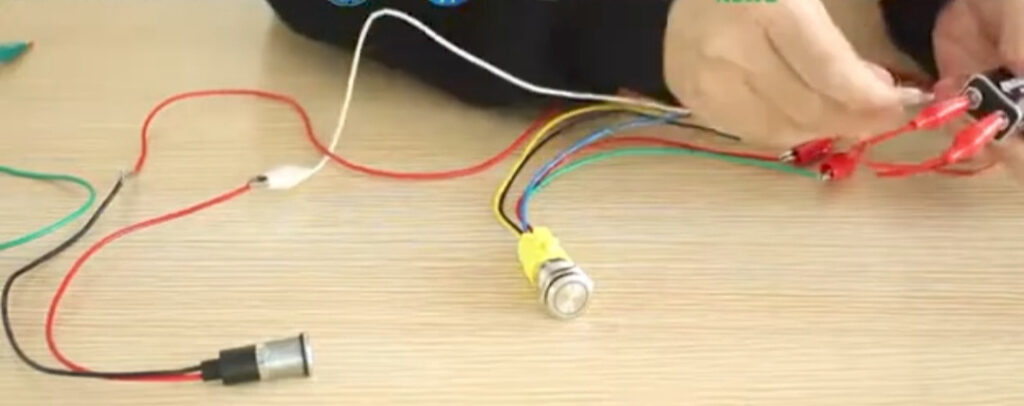 [/vc_column_text][/vc_column_inner][vc_column_inner width=”1/4″][vc_column_text css=””]Step 3: Link Other Side of the Device
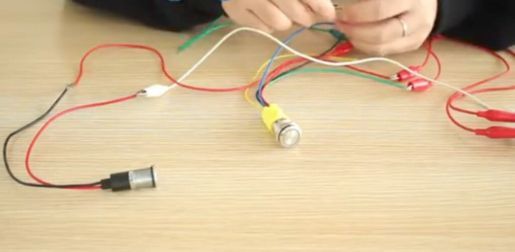 [/vc_column_text][/vc_column_inner][vc_column_inner width=”1/4″][vc_column_text css=””]Step 4: Attach Another Wire
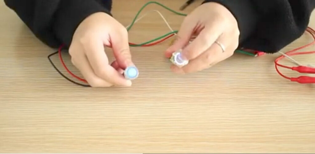 [/vc_column_text][/vc_column_inner][vc_column_inner width=”1/4″][vc_column_text css=””]Step 5: Test the Circuit
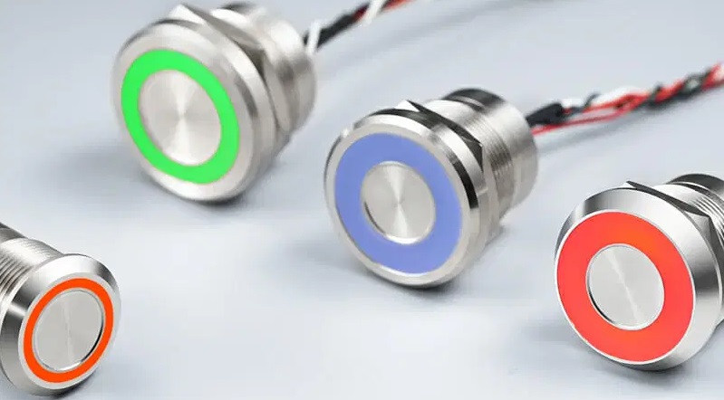


 [/vc_column_text][/vc_column][vc_column width=”1/5″][/vc_column][/vc_row][vc_row][vc_column][vc_column_text]
 [/vc_column_text][/vc_column][vc_column width=”2/3″][vc_column_text]
 [/vc_column_text][/vc_column][vc_column width=”2/3″][vc_column_text]
 [/vc_column_text][/vc_column][vc_column width=”2/3″][vc_column_text]
 [/vc_column_text][/vc_column][vc_column width=”2/3″][vc_column_text]
 [/vc_column_text][/vc_column][vc_column width=”2/3″][vc_column_text]
 [/vc_column_text][/vc_column][vc_column width=”2/3″][vc_column_text]
 [/vc_column_text][/vc_column][vc_column width=”2/3″][vc_column_text]
 [/vc_column_text][/vc_column][vc_column width=”2/3″][vc_column_text]
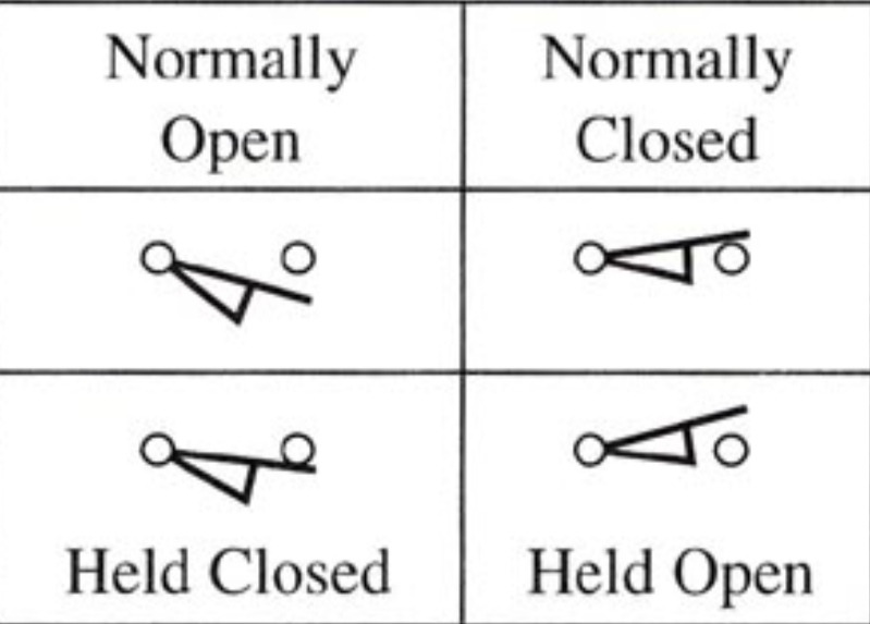 [/vc_column_text][/vc_column][vc_column width=”2/3″][vc_column_text]
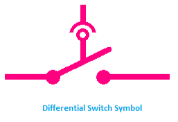 [/vc_column_text][/vc_column][vc_column width=”2/3″][vc_column_text]
 [/vc_column_text][/vc_column][vc_column width=”2/3″][vc_column_text]
 [/vc_column_text][/vc_column][vc_column width=”2/3″][vc_column_text]
 [/vc_column_text][/vc_column][vc_column width=”2/3″][vc_column_text]
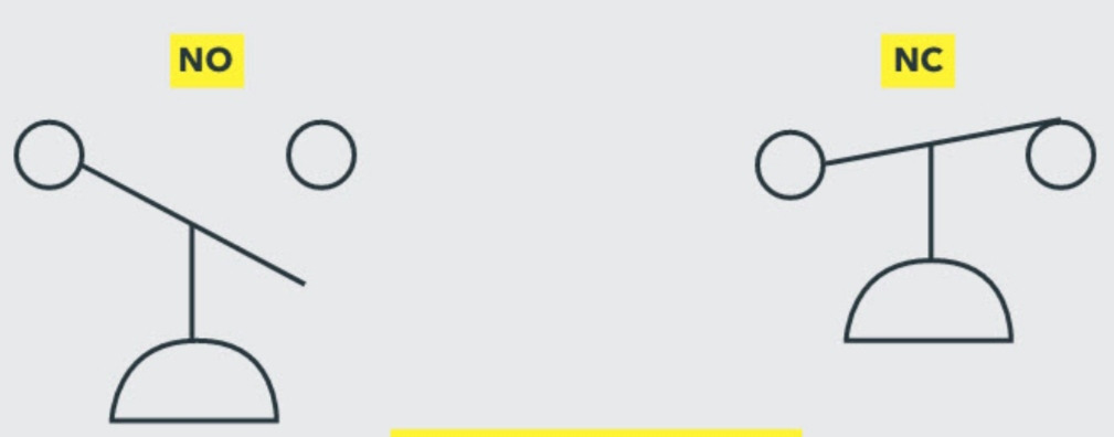 [/vc_column_text][/vc_column][vc_column width=”2/3″][vc_column_text]
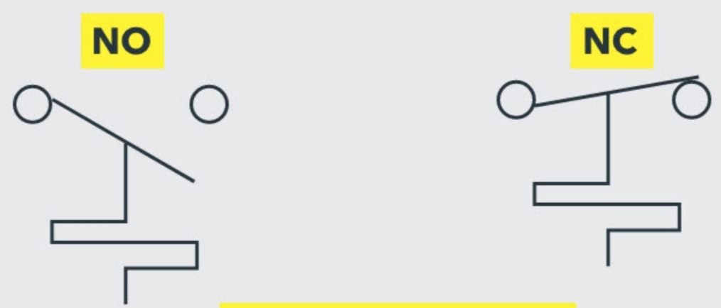 [/vc_column_text][/vc_column][vc_column width=”2/3″][vc_column_text]
 [/vc_column_text][/vc_column][vc_column width=”2/3″][vc_column_text]
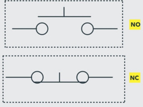 [/vc_column_text][/vc_column][vc_column width=”2/3″][vc_column_text]
 [/vc_column_text][/vc_column][vc_column width=”2/3″][vc_column_text]
 [/vc_column_text][/vc_column][vc_column width=”2/3″][vc_column_text]
 [/vc_column_text][/vc_column][vc_column width=”2/3″][vc_column_text]
 [/vc_column_text][/vc_column][vc_column width=”2/3″][vc_column_text]
 [/vc_column_text][/vc_column][vc_column width=”2/3″][vc_column_text]
 [/vc_column_text][/vc_column][vc_column width=”2/3″][vc_column_text]
 [/vc_column_text][/vc_column][vc_column width=”2/3″][vc_column_text]


 [/vc_column_text][/vc_column_inner][vc_column_inner width=”1/5″][/vc_column_inner][/vc_row_inner][/vc_column][/vc_row][vc_row][vc_column][vc_column_text]